In a binary number, leading zeros are the zero digits in the most significant positions of data, up to the position in which the first one is present. For a binary number  the leading leading zero count is 4. Leading zero counter is a very important combinational circuit in designing the floating-point architectures to do the normalization operation.
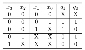
Here an architecture to count maximum 15 leading zeros is presented. A simple modular architecture is presented in [1]. In [1], authors designed higher order leading zero counter using 4-bit leading zero counters. In a binary number (  ), the leading zero count (
  ) varies from 0 to 3. If all the bits are zero then it generates a signal (
  ) to indicate that the number is zero. The truth table for 4-bit leading zero counter (LZC-4) is shown below in Table 1.
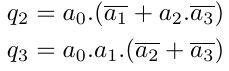
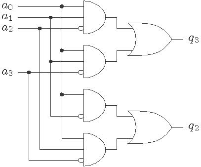
Using the K-map optimization technique the Boolean expression for the outputs of LZC-4 can be obtained and these are
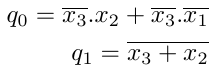
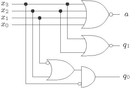
The architecture of the LZC-4 is shown in Figure 1 . It outputs two bits  and also output an signal which indicates that all the bits are zero.
Higher order leading zero counters can be designed using the basic LZC-4 blocks. The four bits are together called as nibble. A 16-bit binary number has four nibbles. The outputs  and
and  is generated by the
  nibble from the MSB side. Lets consider to design a LZC-8 block to count 7 leading zeros. In this case, the count will vary from 0 to 7. If
  , the zero count value depends on
  and if
  then
then  decides the overall count value. The truth table for 16-bit leading zero counter (LZC-16) is shown in Table 2.
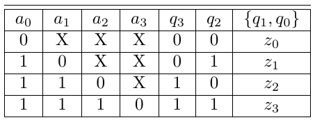
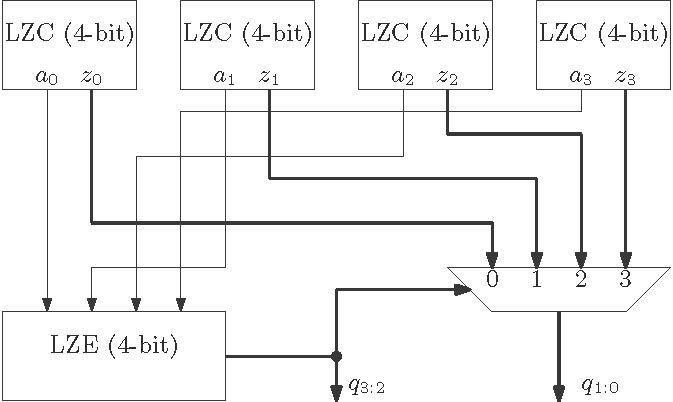
The LZC-16 is designed using the basic LZC-4 block. The upper bits of the counter are evaluated by a block which takes the inputs from the LZC-4 blocks. This block is called as leading zero encoder (LZE-4) which is shown in Figure 2. The logical expressions for the outputs of this blocks are decided by the Table 2 . Using K-map the logical expressions are defined as
Finally the overall architecture of LZC-16 is shown in Figure 3 . There are four LZC-4 blocks used here and one LZE block is used. The output of the LZE-4 block which are the upper bits of the counter selects the lower bits trough a MUX.
[1]. Nebojša Z. Milenković and Vladimir V. Stanković and Miljana Lj. Milić, “MODULAR DESIGN OF FAST LEADING ZEROS COUNTING CIRCUIT”, Journal of ELECTRICAL ENGINEERING, VOL. 66, NO. 6, 2015, 329–333