Contents for the system architectures are
Based on the signal acquisition strategy, area and timing constraints digital system architectures can be of the following types
- Serial Architectures
- Parallel Architectures
- Mixed Architectures
Serial Architectures
The serial architectures process a data stream serially by taking one data at a time. Depending on the type of data, serial architectures can also be subdivided into word serial and bit serial architectures. Obviously, these types of architecture take huge time to process all the data in a stream but consume less hardware. An example of a serial architecture is shown below. Input ‘a’ is a serial data stream. The mean value of 8 data inputs is to be calculated. In each clock cycle, one data is passed to the adder block. Taking one data in each clock the architecture calculates mean of 8 input data in 8 clock cycle. The RSH3 block is a wired shift to implement division by 8, discussed in the post for Combinational Circuits. For the next set of 8 input data, a reset input ‘s’ clears the register involved in accumulation. The adder subblock is an 18-bit parallel ripple carry adder.
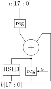
Figure 1: Computation of mean of 8 data inputs from the serial data stream
module serial(a,b,clk,s);

input [17:0] a;

output [17:0] b;

input clk,s;

wire [17:0] t1,t2,a1;

wire co;

parameter cin = 1'b0;

reg18 m1(a1,clk,1'b0,a);

adder_18 m2(a1,t2,cin,t1,co);

reg18 m3(t2,clk,s,t1);

rsh3 m4(t1,b);

endmodule
So, in this type of architecture 8 clock cycles are needed to compute mean of 8 serial data inputs.
Parallel Architecture
The problem of calculating mean of 8 data inputs is solved here using a parallel architecture. Here the data stream is parallel. There are 8 parallel input lines. In each clock cycle, 8 data inputs are available to the architecture. The parallel architecture is shown below.
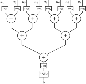
Figure 2: Mean computation of 8 parallel data inputs.
module parallel(a1,a2,a3,a4,a5,a6,a7,a8,clk,b);

output [17:0] b;

input clk;

input [17:0] a1,a2,a3,a4,a5,a6,a7,a8;

wire [17:0] t1,t2,t3,t4,t5,t6,t7,t8,

t9,t10,t11,t12,t13,t14,t15,t16;

wire c1,c2,c3,c4,c5,c6,c7;

parameter cin = 1'b0;

////input stage registers.....

reg18 m1(t1,clk,reset,a1);

reg18 m2(t2,clk,reset,a2);

reg18 m3(t3,clk,reset,a3);

reg18 m4(t4,clk,reset,a4);

reg18 m5(t5,clk,reset,a5);

reg18 m6(t6,clk,reset,a6);

reg18 m7(t7,clk,reset,a7);

reg18 m8(t8,clk,reset,a8);

////adder tree

adder_18 m9(t2,t1,cin,t9,c1);

adder_18 m10(t4,t3,cin,t10,c2);

adder_18 m11(t6,t5,cin,t11,c3);

adder_18 m12(t8,t7,cin,t12,c4);

adder_18 m13(t10,t9,cin,t13,c5);

adder_18 m14(t12,t11,cin,t14,c6);

adder_18 m15(t14,t13,cin,t15,c7);

////output stage registers.....

reg18 m16(t16,clk,reset,t15);

////wired division by 8

rsh3 m17(t16,b);

endmodule
In this type of architecture, mean of 8 inputs is computed in one clock cycle with the critical path of 3 adders. And the time period of clock cycle depends on the maximum delay of the critical path.
Mixed Architectures
Serial and parallel architectures can be used together in a complex digital system. Some of the sub-blocks can be of serial architecture where speed can be compromised. It is critical to know where to use serial and where to parallel architectures.
Pipelining
The advantage of the parallel architectures is obvious. They are superior to the serial architectures in terms of speed but inferior in terms of hardware. In the previous example, the critical path of 3 adders degrades the performance of parallel architectures. This can be improved by inserting pipeline registers which reduces the critical path to 1 adder delay. The same parallel architecture with pipeline registers is shown below.
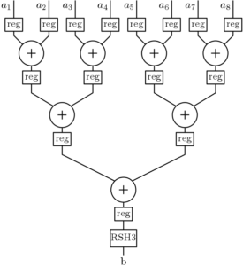
Figure 3: The parallel architecture for computation of mean with pipeline registers.
module mean_pipe(a1,a2,a3,a4,a5,a6,a7,a8,clk,b);

output [17:0] b;

input clk;

input [17:0] a1,a2,a3,a4,a5,a6,a7,a8;

wire [17:0] t1,t2,t3,t4,t5,t6,t7,t8,

t9,t10,t11,t12,t13,t14,t15,t16,t17,

t18,t19,t20,t21,t22;

wire c1,c2,c3,c4,c5,c6,c7;

parameter cin = 1'b0;

////input stage registers.....

reg18 d1(t1,clk,reset,a1);

reg18 d2(t2,clk,reset,a2);

reg18 d3(t3,clk,reset,a3);

reg18 d4(t4,clk,reset,a4);

reg18 d5(t5,clk,reset,a5);

reg18 d6(t6,clk,reset,a6);

reg18 d7(t7,clk,reset,a7);

reg18 d8(t8,clk,reset,a8);

////adder tree

adder_18 m1(t2,t1,cin,t9,c1);

adder_18 m2(t4,t3,cin,t10,c2);

adder_18 m3(t6,t5,cin,t11,c3);

adder_18 m4(t8,t7,cin,t12,c4);

//1st stage pipeline registers.

reg18 d9(t13,clk,reset,t9);

reg18 d10(t14,clk,reset,t10);

reg18 d11(t15,clk,reset,t11);

reg18 d12(t16,clk,reset,t12);

adder_18 m5(t14,t13,cin,t17,c5);

adder_18 m6(t16,t15,cin,t18,c6);

//2nd stage pipeline registers.

reg18 d13(t19,clk,reset,t17);

reg18 d14(t20,clk,reset,t18);

adder_18 m7(t19,t20,cin,t21,c7);

////output stage registers.....

reg18 d15(t22,clk,reset,t21);

////wired division by 8

rsh3 m8(t22,b);

endmodule
Key parameters
Some key terms are defined to describe the architectures which are.
Latency:- It is the time period after which the architecture produces its first relevant output.
Throughput:- This is the number of outputs produced by an architecture per clock cycle.
Maximum Frequency:- This is the value of maximum frequency that can be achieved by an architecture.
Comparison
A simple comparison of these 3 type of system architectures is shown below. A more detailed comparison will be shown in the next posts.
Table 1: Comparison of different architectures for computation of mean of 8 data inputs.
| Parameters | Serial | Parallel | Parallel with Pipeline |
| Registers | 2 | 9 | 15 |
| Adders | 1 | 7 | 7 |
| Latency (clk) | 9 | 2 | 4 |
| Throughput | 1/8 | 1 | 1 |
| Max. Frequency (MHz) | 132 | 62 | 132 |
The type of digital system architecture depends on some considerations which are
- Data acquisition system
- Speed requirement
- Area constraint
These above-mentioned considerations are interrelated. If the data acquisition system is serial, then the system architecture is bound to be serial unless there is serial to parallel conversion. If the required speed is not high enough then serial systems can be afforded. For complex systems, area constraint also forces a system to be a serial one. Serial and parallel architectures can exist in a single system depending on the requirement. On the other hand, for high speed, demand pipeline architectures must be adopted to increase the maximum achievable frequency and throughput.
Click here to download the file