Booth’s algorithm is a powerful technique to achieve fast multiplication. Booth’s algorithm can be employed either sequentially or with the help of fast addition methods or in the form of array multiplication. In this tutorial, Booth’s Radix-4 algorithm is used to form an architecture to multiply two 6-bit numbers in the form of array multiplier.
The Booth’s Radix-4 algorithm is chosen here because it has fixed add/sub and shift operations though the multiplier recoding method is not optimum. In this algorithm, total n/2 add/sub operations are needed. Here the operand are signed and of 6-bits. So total 3 add/sub operations are required. Thus Booth’s array multiplier has three stages.
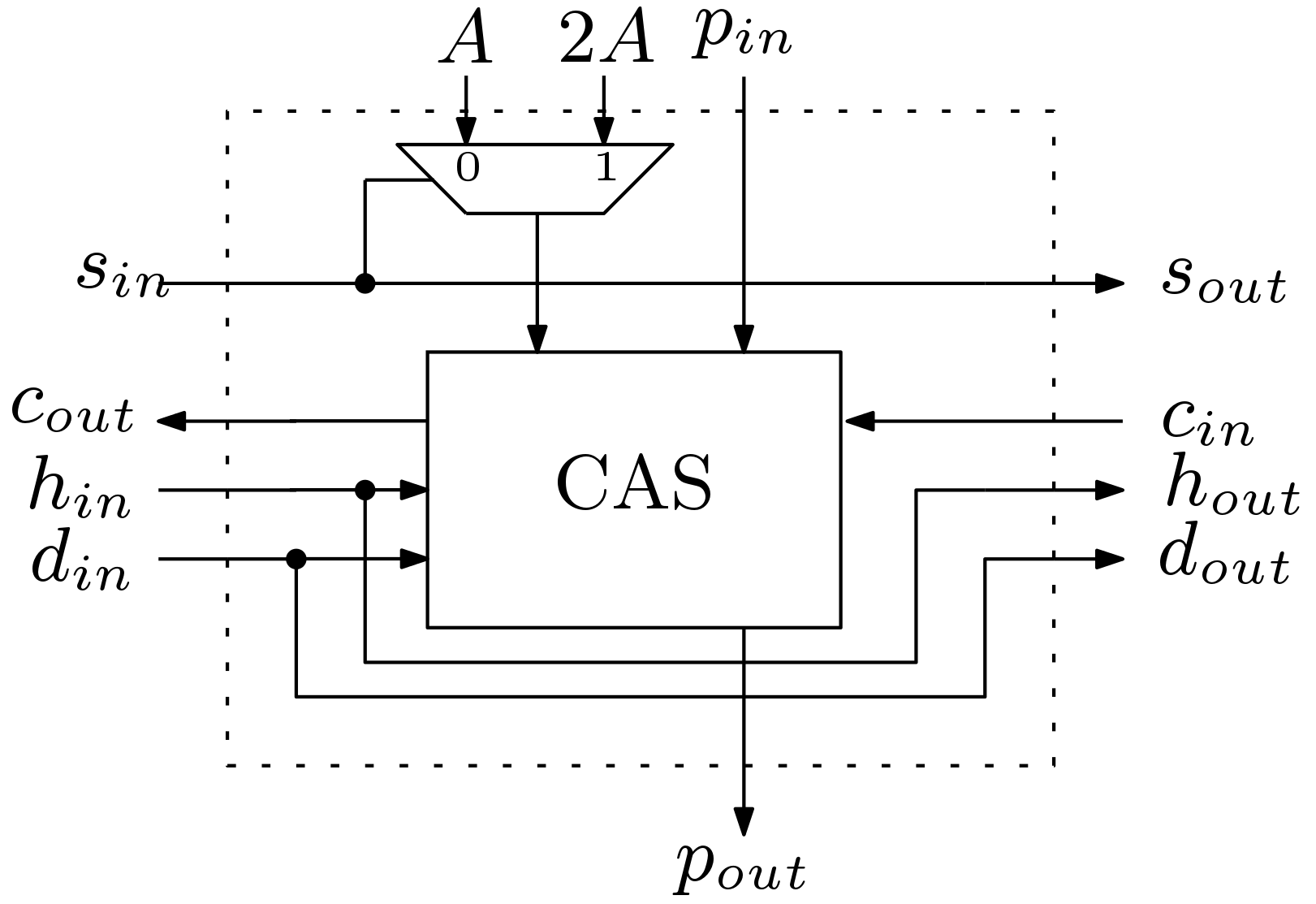
The Booth’s Radix-4 algorithm works on the principle of selecting partial products from the set {A, 2A ,0, -A, -2A}. The partial product 2A can be easily obtained by wired shifting method. Thus we need a selection procedure to select between A and 2A. The block diagram for the basic Sub Block (SB) is shown in Figure 1. Here the input s selects between A and 2A. The major block of the SB is the controlled adder and subtractor (CAS) block. The Boolean expression for the CAS block is


If h=1, arithmetic operation is performed otherwise input is passed to the output. If d = 1, subtraction operation is performed and input a is subtracted from  . Then
  is the incoming borrow and
  is the outgoing borrow. If d = 0, addition operation is performed and input a is added with .
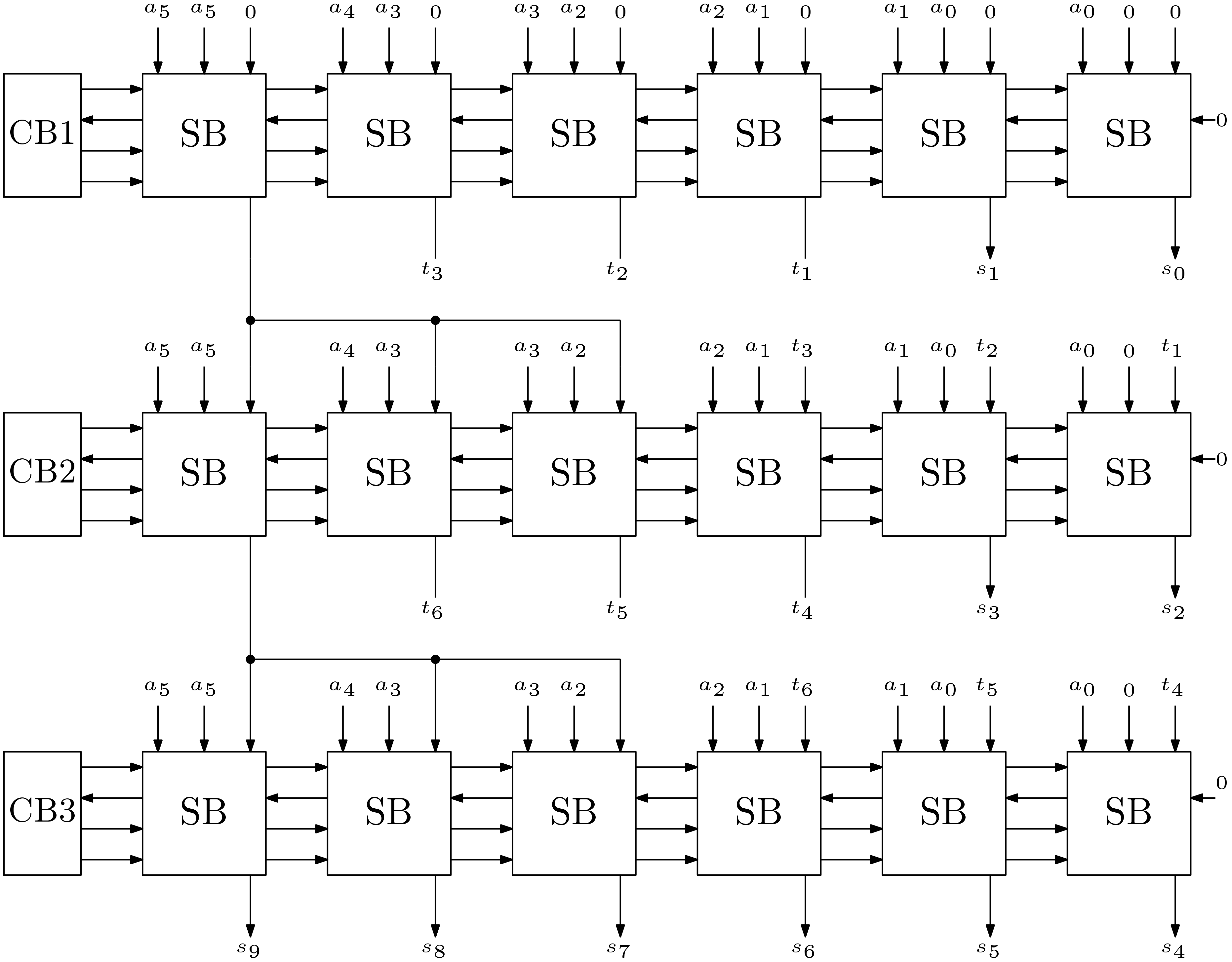
The overall Booth’s array multiplier for 6-bits is shown in Figure 2. This multiplier is capable of performing sign multiplication without any extra hardware. The control signals are generated from the Control Blocks (CB). Total 18 SBs are used in this design.
Control Block design: The generation of the control signals is important. Three control signals are used in this design which are s, h, d. The truth table for this control signals according to the input data X is shown below in Table 1.
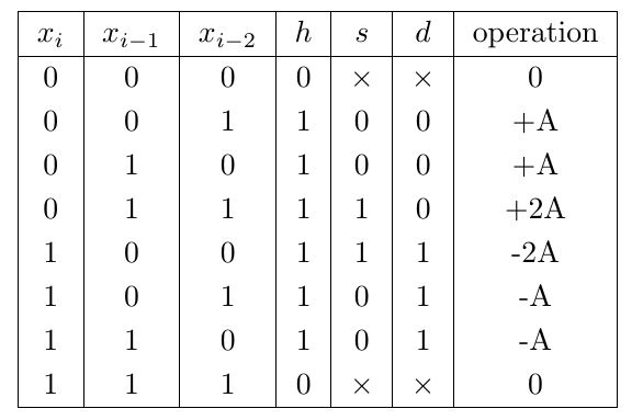
Boolean expressions for the control signals can be obtained by applying Karnaugh map. The logical expressions are obtained as


Here i took the value from the set {1, 3, 5, ……}.
Click here to download the Verilog code.
This is in 6 bit, can we convert the code into 4 bits? I need it for my project