QR decomposition is one of the powerful matrix factorization techniques that is used to solve a linear equation, to find matrix inverse or to find pseudo-inverse. In this factorization technique, a matrix (A) is factorized into two matrices Q and R such that A = QR. Here, Q is an ortho-normal matrix and R is an upper triangular matrix. QR decomposition can be achieved mainly by three techniques which are House Holder technique, Gram-Schimdt technique and Givens Rotation technique. Over the many decades, many modifications are suggested to these techniques. In many applications, real time solution of linear equations is very important. Thus, FPGA Implementation of QR Decomposition is very important. Many architectures are proposed for QR Decomposition over the past few decades. The objective of this article is to provide a tutorial for CORDIC based FPGA Implementation of QR Decomposition. QR factorization is performed based on Givens Rotation in this tutorial.
It is assumed that readers have knowledge of basics of CORDIC block otherwise they are suggested to visit our previous tutorial on CORDIC. In Givens rotation, one element is nullified, and another element gets magnitude of the two elements in order to form an upper triangular matrix. This operation is done by CORDIC block. CORDIC block finds magnitude of two elements in vectoring mode in circular version. Pipeline implementation of CORDIC block is adopted here for FPGA Implementation QR Decomposition. One stage of CORDIC is having three adder/subtractors for rotation of vectoring mode. But for QR decomposition, a hardware efficient architecture is proposed in [1]. This tutorial is based on the CORDIC block architecture mentioned in [1] where a stage of CORDIC uses only two adder/subtractors.
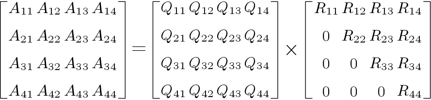
Example of QR decomposition for a  matrix is shown below in Figure 1. Here, input matrix A is factorized in two matrices Q and R. In Givens Rotations technique, upper triangular matrix R is obtained by performing Givens Rotations on input matrix, but matrix Q is obtained by performing Given rotations on identity matrix of same size.
 matrix.
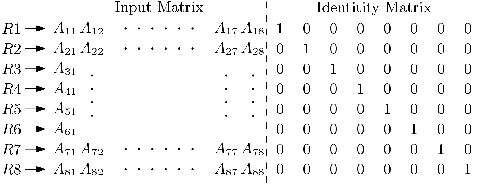
In this tutorial, we will be trying to factorize a  matrix. In Figure 2, input matrix along with identity matrix is shown. There is total 8 rows. CORDIC block operates on any two rows in one go. If only upper triangular matrix (R) is required, then there is no need to send the identity matrix. After the Given rotation operation, the Input matrix will be transformed to the upper triangular matrix and the identity matrix will be transformed to the matrix Q.
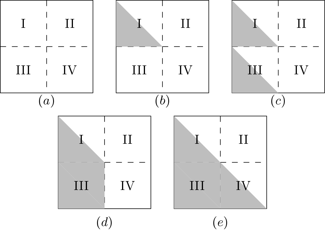
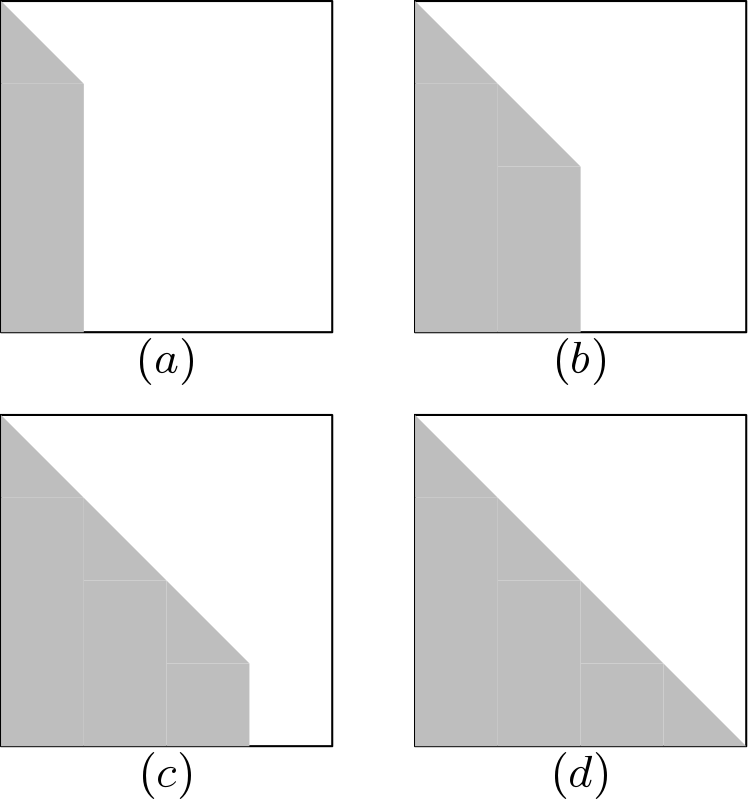
QR decomposition strategy on matrix is shown below in Figure 3. Whole matrix is divided into 4 parts. QR decomposition for matrix can be achieved in four steps. All these steps are mentioned below by gray color. Two types of QR blocks are designed to perform FPGA Implementation QR Decomposition and they are QR_part1 and QR_part2. In the first step, R1-R4 are passed to the QR_part1 block and they got modified to  . QR_part1 block nullify 6 elements. Gray area in section I denotes the elements which are zeroed by the QR_part1 block. In the second step, R5-R8 are passed to the to QR_part1 block and got modified to
  . Gray area in section III denotes the elements which are zeroed by the QR_part1 block. In the third step, the non-zero elements (upper triangular matrix having 10 elements) in section III should be nullified. In order to nullify these elements, another QR block is used which is called QR_part2. These elements are nullified with the help of . Thus, in this step, are modified to
  . At the final step, section IV is converted into an upper triangular matrix by the QR_part1 block. In this step, get modified to
  by the QR_part1 block.
 matrix.
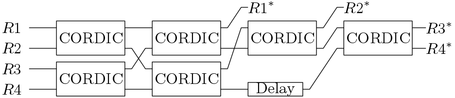
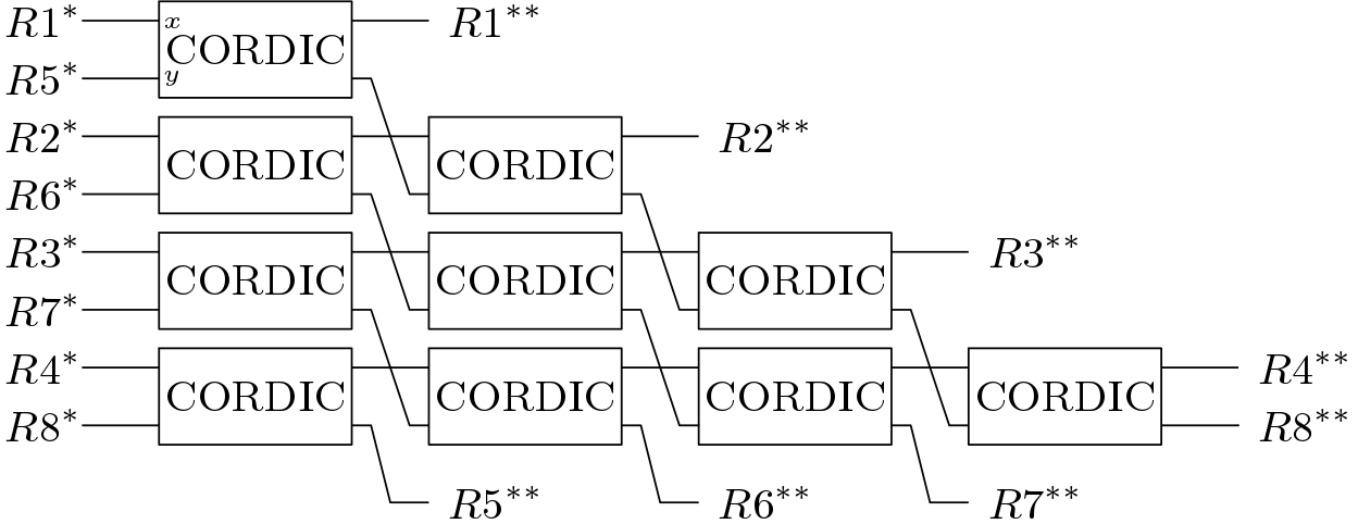
In order to perform QR decomposition efficiently on any square or rectangular matrix, both QR_part1 and QR_part2 sub-blocks are necessary. QR_part1 block performs QR decomposition on a matrix. More details on this block can be found in [1]. This block operates on four rows and nullifies the 6 elements in lower triangular area. Verilog code for this block is given below at the end of the tutorial. This QR_part1 block has latency of total 4 times the latency of one CORDIC block (21 clock cycles). Delay block is basically used to delay the input by one CORDIC latency. These CORDIC blocks operates based on a start signal which flows from input to output. This start signal should be synced with the element which is required to nullified.
 matrix.
The above-mentioned sub-block is not enough to perform the QR factorization on a bigger matrix greater than size . Above strategy can be used for QR factorization of matrix but in this case many CORDIC blocks will be required. QR_part2 block used to nullify the 10 elements arranged in upper triangular shape. Same CORDIC blocks are used here. In case of matrix, are modified with respect to . The symbol (*) indicates modification after one CORDIC rotation. Total latency of this block is 4 times the latency of one CORDIC.
The advantage of using two kinds of QR blocks for FPGA Implementation QR Decomposition is that QR_part1 and QR_part2 block can operate simultaneously. Like in Figure 2, QR_part1 and QR_part2 both are simultaneously used to nullify the elements of section III. In case of bigger matrix, advantage of using two kinds of QR blocks is more visible. QR strategy for  matrix is shown below in Figure 5.
 matrix.
Verilog code of individual blocks are provided below but QR decomposition of the whole QR decomposition architecture is not provided. Only the strategy is given here as user may need different strategy for their application. It is hoped that students may be able to use these two blocks for better architecture of QR decomposition. Even they can modify the blocks also.
Reference
1. Sergio D. Muñoz and Javier Hormigo,”High-Throughput FPGA Implementation of QR Decomposition”, EEE TRANSACTIONS ON CIRCUITS AND SYSTEMS—II: EXPRESS BRIEFS, VOL. 62, NO. 9, SEPTEMBER 2015