Power consumption is an important key design metric to determine performance of a chip. In VLSI circuit point of view, total power consumption can be due to various factors. In general total power consumption is summation of static power consumption ( ) and dynamic power consumption (
 ) . But in this section as we focuses on the gate level implementation of VLSI circuits, we will only discuss dynamic power consumption. Dynamic power consumption can be expressed as

Thus Dynamic power consumption is directly proportional to the signal switching frequency ( ). Thus as the operating frequency increases, dynamic power consumption increases but static power (
 ) is remain fixed.
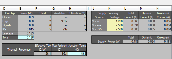
In this section we will discuss how to estimate dynamic power consumption of a digital design. Every emulation softwares provide tools to estimate power. As we are initially implementing digital designs using XILINX software, we will discuss power estimation using XILINX. XILINX provides XPower analyzer tool to estimate power. We discuss the power consumption of the same circuit which is implemented in FPGA implementation section. In this section XILINX 14.7.
Steps to Estimate Power
- The design should be fully routed and all the constraints should be met.
- In XILINX ISE software window, go to tools and open XPower analyzer.
- In XPower analyzer window, File > open design.
- Insert appropriate file and it will automatically show the power consumption report.
Required Files
- Design File (.ncd) – The XPA needs an Native Circuit Description (. ncd) file. This file contains the logic of your design mapped to components (such as CLBs and IOBs). It is generated during the implementation process.
- Settings file – The Settings file contains application settings and node activity rates saved from an XPower Analyzer session. Any manual changes (edits) you have made in the XPA window can be saved to a settings file. The settings file (in XML format) can then be used to load any relevant design information from a previous XPA session into a later session.
- Constrains File – This is an optional file. The PCF (Physical Constraints File) contains constraint information to determine clock frequencies. All clock information from the UCF (User Constraints File) is reported in the PCF. If the design is well constrained, loading the PCF is important for accurate power results.
- Simulation Activity File – Two types of optional files are there, viz., The Switching Activity Interchange format (SAIF) and Value Change Dump (VCD). These simulation activity files include specific switching information (toggle rates, signal rates, and frequency information) that will give the most accurate power estimation. Note that XPA might not always be able to match all of your design nets with nets in the simulation file so you may have to enter some switching information manually. It is important to make sure you look at what design information was pulled in and what (if any) design information was not pulled in. In the Console window take note of any warning messages, since they may indicate that design information was not pulled into XPA.
Creating the simulation Activity file
To create .vcd file type the following in testbench…
initial begin
$dumpfile ("test_design.vcd"); // Change filename as
appropriate.
$dumpvars(1, test_tb.uut);
end
here test_tb is the test bench file name and test_design is the file name.
It is to be remembered that XILINX does not provide the accurate power estimate. In order to estimate the accurately measure the power there are other emulation softwares like Cadence, Synopsis etc. But for FPGA implementation this may give an closer estimation of dynamic power consumption. We can consider changes PVT parameters and give input to the XPA. The XPA can save these user settings in a XML file for accurate measure of power.