Our objective is to divide A by B where both A and B can be positive or negative. The division operation can be expressed as by the following equation by considering 4 bit data width.
![]()
where Q is the quotient and R is the remainder. The division operation is carried out by subsequent stages where each stage determines a quotient bit. Thus it is called an array divider.
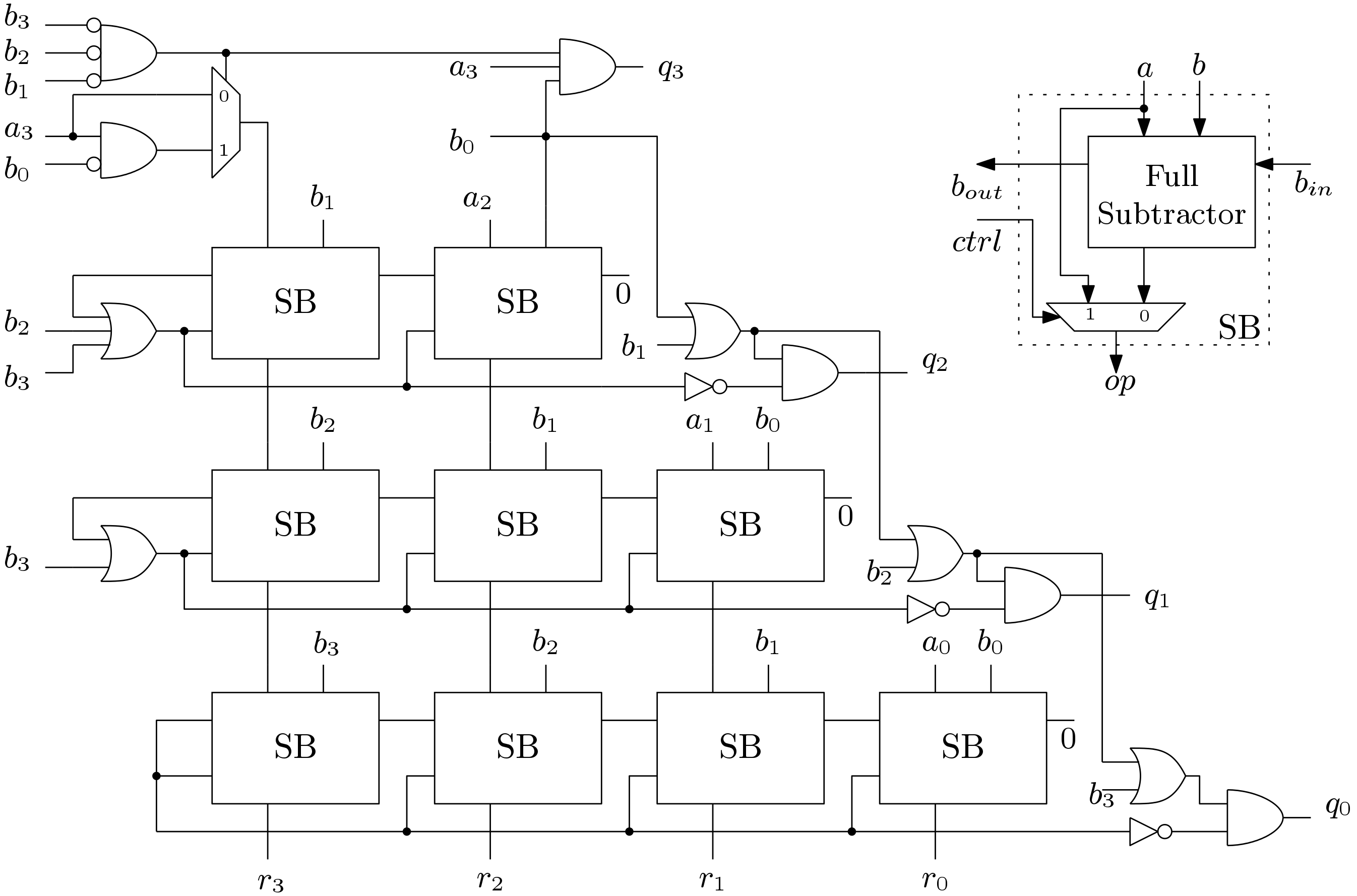
In the first stage to find the bit Q3, B is left shifted by 3 bits and subtracted from A. The quotient bit Q3 is 1 if the difference is zero or positive. If the difference is negative, Q3 is 0 and the value of A is passed to the next stage. This technique is simply the restoring division discussed in the previous post. The division operation is explained by an example where A = 1100 and B = 0010. The unsigned divider for 4-bit data width is shown below.


From the above example it is clear that to compute Q3, B0 is subtracted from A3 only when other bits of B are zero. This logic is implemented in the first stage. Similarly to compute Q2, bits B1 and B0 are needed to be subtracted thus two sub blocks are used. The block diagram of the sub block is also given in the above figure. It consists of a full subtractor and a Mux.
The above example is shown for division by unsigned numbers. The signed division can be done easily by adopting this division method. The input signed operands (Two’s compliment representation) are needed to converted to unsigned operands and at the output the quotient and residual are also needed to be converted to signed operands depending on the sign of input operands.
The above divider produces a quotient (Q) and remainder (R) but the practical use of divider involve generation of fractional bits. A Verilog code of a complete pipelined 18-bit signed divider is given in this bit. 8-bits are used for integer part and 10-bits are used for fractional part. To generate fractional result, 10 more stages are added to the previous stages. This divider can be modified accordingly to requirement of quotient and fractional bits.

can you give us please 1 or 2 examples for the division of the above figure you proposed? thank you
Yes I could give more examples… But you can better download the code and try simulating…
I want to implemented the figure of the array divider you have proposed rather than the divider of 18-bit numbers.
Then you have under stand the code. For less number than 18, some of the stages will be removed and you have to adjust pipelining accordingly.
I want to implement the 4 bit divider of the figure.
I think code is given.
A 4 bit divider will do the work.
Thank you so much for this. Works as expected !!
Where’s the Download link, PLS.
It is below the post…..
I cant find “Click here to download the Verilog code.” in this post 🙁
Hello, first of all thanks for this great publication, it has been a great help to me.
Is it possible to implement this divider for 6-bit numbers?
If u have understood the architecture, u can design it for any bits. Site has code for 18 bit unsigned divider.
I understand that I have to put more rows and columns of subtractors and it is what I am implementing but I do not understand what to do with the first AND gate where the bits of B are if I want to use 6 bits
one clue i can give..like in the first AND gate inputs will be b1 to b5…..for 6bit divider.
hello, its possible to get the code ? thanks
https://digitalsystemdesign.in/product/18-bit-radix-2-unsigned-binary-divider/
Her you can find the detailed code..
Isn’t the first and gate a direct nand ?. If so, is it better to use nots and “and” or a single NAND
It is not equivalent to direct NAND.. Try de Morgan’s law.. May be replaced by NOR..