A numerically controlled oscillator (NCO) is used for on-chip generation of major signals like cosine, sine, linear frequency modulated (LFM), Gaussian etc. in system on chips (SoCs). These signals can be generated by two ways, either by analog circuitry or by digital circuitry. In a digital system, these signals are generated using numerically controlled oscillator (NCO) and then they are converted by an digital to analog converter (DAC).
An NCO block is a digital counter part of an analog oscillator circuit. There are two types of NCO designs available. In one type of NCO block, sinusoidal values are computed by a dedicated hardware like coordinate rotation digital computer (CORDIC). In another type of NCO block, a look up table (LUT) is used to store a sinusoidal signal of fundamental frequency ( ) and sinusoidal signals of other frequencies are generated using the sinusoidal signal which is stored.
LUT based NCO blocks are very simple but have some disadvantages. Like they are not capable of generating sinusoidal signals of any frequency. But LUT based NCOs are hardware efficient than the other type of NCO block. Thus LUT based NCOs are mostly used because of their simplicity. In this work, we will be focusing on designing an efficient LUT based NCO block to generate cosine or sinusoidal signals. The LUT based NCO block is implemented on Artix 7 field programmable gate array (FPGA)
Numerically Controlled Oscillator Block Operation
The principle of operation of a LUT based NCO is based on generating the cosine signal as per the following equation
(1) 
where  is the length of the signal and it varies from 1 to 1024 in this design. The cosine signal of fundamental frequency () can be obtained by putting
  in equation (1). This cosine signal of fundamental frequency () is stored in a LUT. Other cosine signals with frequencies
  etc. can be generated easily from the stored cosine signal. The fundamental cosine signal is shown in Figure 1.
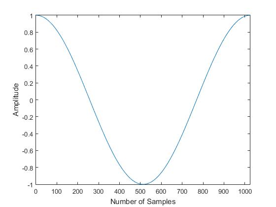
The cosine signal with fundamental frequency () can be stored in the LUT in three ways. Either by storing the whole length of the signal, or storing half of the signal, or by storing only one fourth of the cosine signal. This is possible due to symmetric and antisymmetric property of the cosine pulse. The third option is chosen here to design the NCO as to reduce the memory storage elements from to  .
.
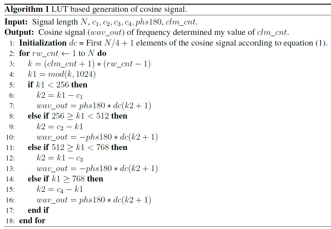
Sinusoidal signals of different frequencies can be easily generated if the whole fundamental cosine signal is stored in LUT. But it is difficult to generate cosine signals if only  elements of the fundamental cosine signal is stored. The algorithm to generate cosine signals of different frequencies from the fundamental cosine signal is shown in Algorithm 1. In LUT,
  elements of fundamental cosine signal is stored. The variable
  varies from 1 to N and
  can be varied from 0 to
  . The
. The  signal is used to get 180 degree out of phase cosine signals. Algorithm to generate sinusoidal signal is very similar to Algorithm 1.
Architecture of the Numerically Controlled Oscillator
The block diagram of the NCO is shown in Figure 2. The major inputs to the block diagram are ,  ,
,  ,
,  ,
,  and signal.
  denotes the required period of the waveform, signal is used to apply required phase shift, pulse starts the NCO and a pulse at input can stop the NCO. Two types of signal generation are possible with this NCO, one is sine and another is cosine. The type of the signal is given at input. If this signal is high then sine signal is output and if low then cosine signal is out. If instant 180 degree phase shift is required then it is possible by making the signal high.

Major outputs are  ,
,  and
and  . The pulse indicates that the waveform is getting out of the NCO block. NCO outputs the wave form through the signal and it is of 18-bit width. The signal when delayed by two clock cycles, indicates the end of a cycle. If only one cycle is required then signal can be connected to the input.
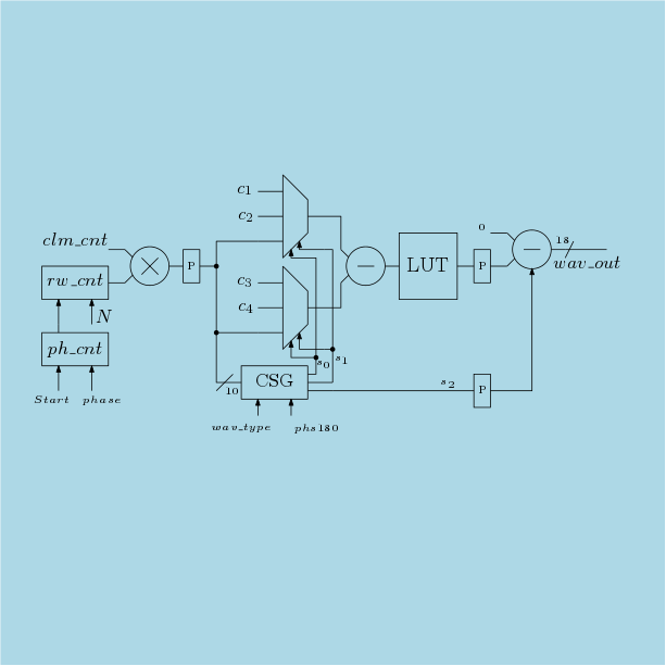
The architecture of the NCO block is very simple and it is shown in Figure 3. The pulse starts the phase counter ( ) and then if the required phase count is reached, another pulse is generated which starts the row counter (). Then the row counter starts counting and it counts upto . The output of the row counter and the input is multiplied.
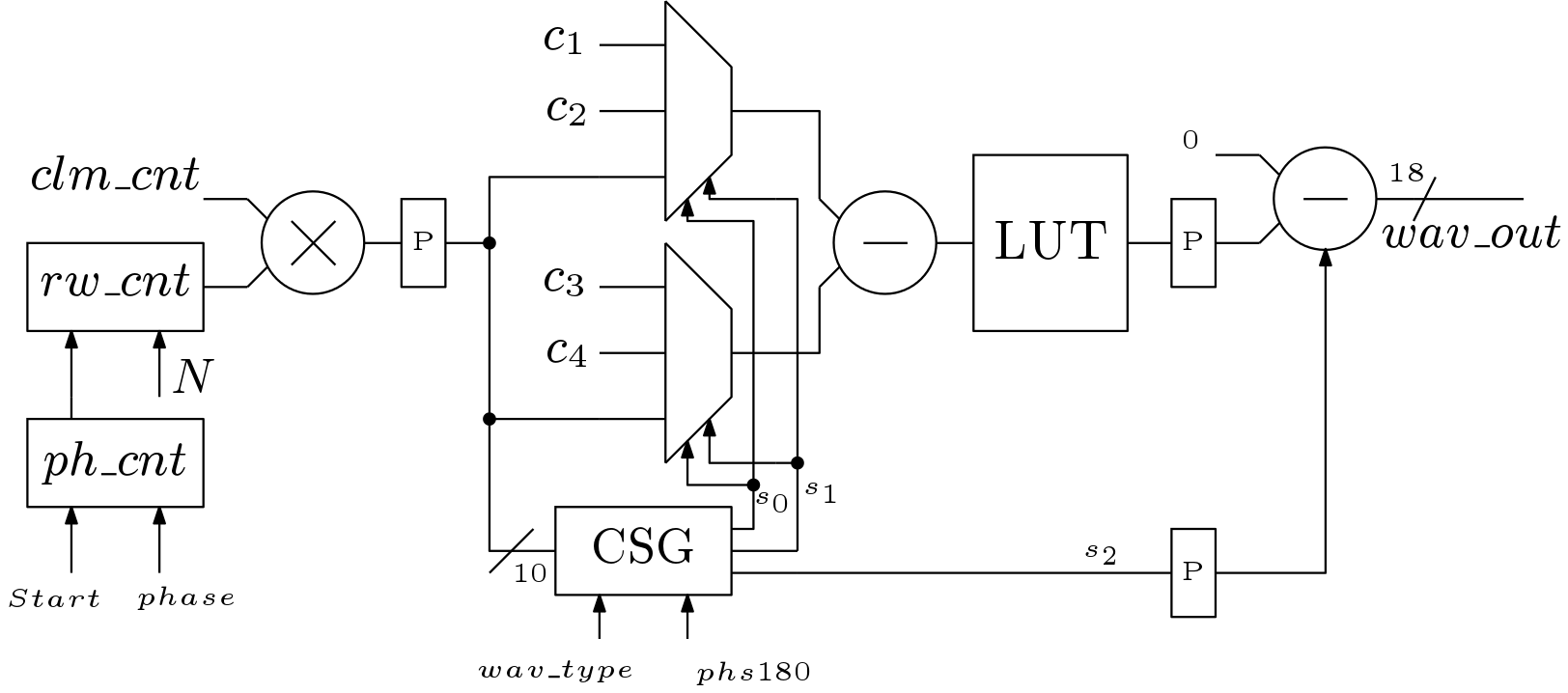
After the multiplication operation, a modular operation is carried out. The modular operation on the output of the multiplier is carried out by taking only 10-bits from the output of the multiplier. This output is then goes to the multiplexers and the output of the multiplexers are fed to a subtracter. The values of the constants for cosine signal are  and
and  . Value of these constants for sinusoidal signal generation are
  and
and  .
.
The multiplexers are used to generate the correct address locations for the LUT. The control signals for the multiplexers are generated from the control signal generator (CSG) block. At the last stage, an inverter is placed to invert the output of the LUT when it is required. This inverter is implemented by a adder/subtracter block. The output of the NCO is of 18-bit as many designs uses 18-bit data width.
Simulation Results
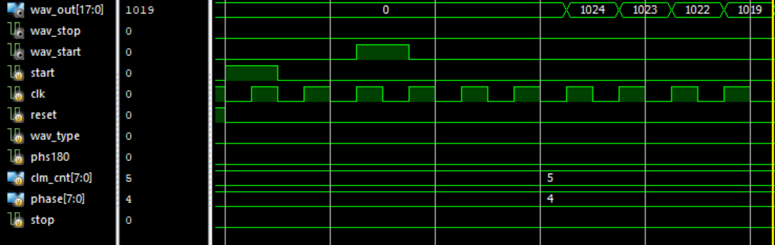
The NCO block is implemented using the XILINX ISE EDA software. The simulation results are shown in Figure 4 and 5. In the Figure 4, it is shown that the cosine signal is generated when the signal is asserted. Here no phase shift is given. In Figure 5, the value of the is 4 and this is why the cosine signal started after 4 clock cycles from the time when signal asserted. Precision of the NCO block is of 10-bit as most of the designs are using this precision.

 is varied from 0 to 7.
Generation of signals with frequency difference  is also possible when is less than 1024. For example, when is 128, the frequency of the fundamental signal is
  for
for  , the frequency of the second signal is
  for
for  , and so on. Thus we can get complete cosine signal when
  with frequency of . This scenario is shown in Figure 6 for
  . The case when
  is very useful in generating atoms of sampling matrix in compressed sensing.
Conclusion
In this work, efficient design of a LUT based NCO block is discussed. The NCO block is hardware efficient in terms of memory elements as it stores only one fourth part of the fundamental cosine signal. This NCO block has the capability to generate both sine or cosine signals. Signals can be phase shifted by any phase from 1 to  . This block is also capable of generating 180 degree out of phase signals without delaying. Besides generating sine or cosine signals of frequency difference , this NCO block is also capable of generating signals with frequency difference for . The proposed design of NCO is scalable thus can be used in any complex digital system easily.
Reference
- D. Hummels, “Numerically controlled oscillators.” [Online]. Available: https://web.eece.maine.edu/~hummels/classes/ece486/docs/NCO_tutorial.pdf
LUT Based Numerically Controlled Oscillator Verilog Code
Product specification
- This is a LUT based Numerically Controlled Oscillator
- This NCO can generate both sine and cosine signal based on a control signal.
- The signals can be delayed or phase shifted by any phase from 1 to N.
- Instant 180 degree phase shift is also possible without delay.
- If N=1024, the cosine signals resembles atoms of FFT dictionary.
- This NCO has 10-bit precision.
- N can maximum value of 1024.
- If N is less than 1024 then frequency difference can be reduced.