K-means algorithm is very popular because of its simplicity. This is an iterative algorithm which tries to partition a dataset into K groups. K-means algorithm tries to group the similar data samples in a cluster in every iteration. This is carried out based on some formulas which computes the similarity between two vectors. This algorithm results K homogeneous groups which are non-overlapping means no data samples can belong to two or more groups.
In many application, real time clustering of the data samples are required. In this context,K-means algorithm is needed to be implemented on some hardware to support real time clustering. In this work, a novel architecture of K-means algorithm is proposed and this architecture is implemented on FPGA based platform. The major objective of this work to present an hardware efficient architecture of K-means algorithm without hampering the execution time.
I. K-means Algorithm
The K-means algorithm is shown in Figure 1. The data set  is taken as input to the K-means algorithm. The algorithm also takes K and I as inputs where K represents the number of clusters and I represents the total number of iterations. This iterative algorithm takes I number of iterations to segregate the data samples in K clusters. Initially the centroids are set as
  for k= 1 to K. Here,
  represents the
  column of A and
  represents the
  centroid.
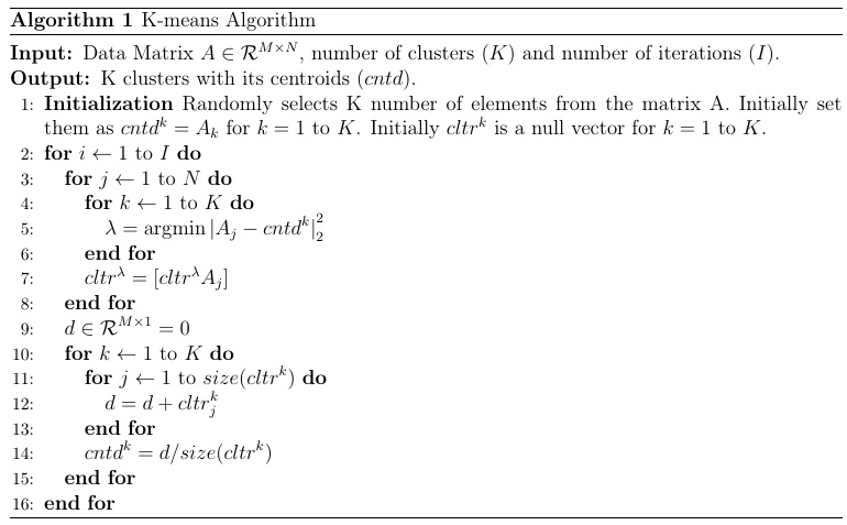
The next step is to find the similarities between the centroids and the columns of A. Similarity can be computed by the techniques such as correlation, euclidean distance and Manhattan distance. In this work, euclidean distance is used to find the similarity between two vectors. The euclidean distance between two vectors of length M can be computed as
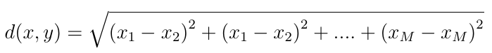
The arithmetic operations involved in computing d(x,y) are subtraction, squaring, addition and square root. The square root operation is complex and thus its hardware complexity is high. In this work, the square root operation is avoided and thus partial euclidean distance is computed. The step 5 in algorithm 1 evaluates this partial euclidean distance. The parameter  represents the index of the column which gives minimum euclidean distance.
Once the similar columns are identified, the cluster formation is done in step 7. The parameter can takes value from 1 to K. Thus there are K clusters possible. The steps 9-15 of the algorithm 1 are for the averaging step. The elements of each cluster are accumulated and result of accumulation is divided by the size of that cluster. After this step, new values of the centroids are computed. The above mentioned steps are repeated for maximum I number of iterations.
II. Proposed Architecture
The proposed data path architecture of the K-means algorithm is shown in Figure 2. In this work, the K-means algorithm is implemented for parameters M = 2, N=8 and K=3. Thus a prototype of K-means algorithm is implemented here but can be adopted for higher data samples. The K-means algorithm has mainly three steps viz., euclidean distance computing, sorting and average computation. These three steps are executed sequentially. In this work, a hardware efficient architecture is proposed which with moderate timing complexity. All the major blocks are explained below.
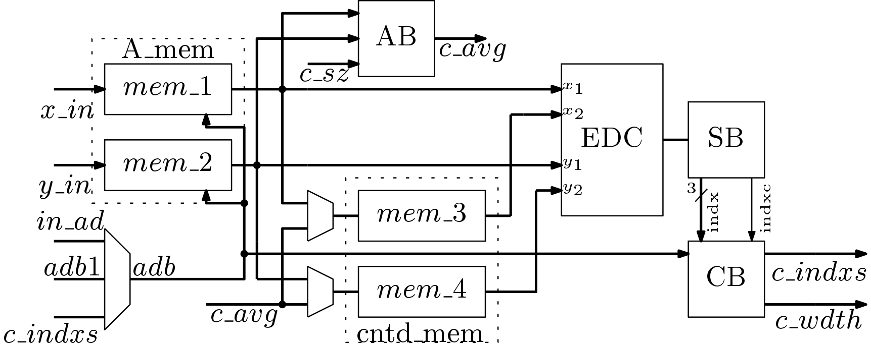
Data Acquisition and Initialization: The input data matrix (A) can be pre-stored or can be acquired in real time. This storing of matrix A is done by  which is a bank of m memory elements. Each memory element is realized using dual port rams. Port A is used for writing and port B is used for reading. In K-means algorithm K elements are randomly chosen. Initially K data samples from the are read and written to
  . This initial indices can be stored in a ROM or generated randomly. This proposed scheme is shown in Figure 2
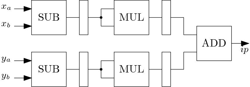
Euclidean Distance Calculator: Euclidean Distance Calculator (EDC) block computes the partial euclidean distance between the centroids and the data samples. The proposed architecture of the EDC is shown in Figure 3. The initial blocks are subtractors and then squaring operation is performed. The square blocks consumes less resources than the multipliers. The outputs of the multipliers are input to an adder tree.
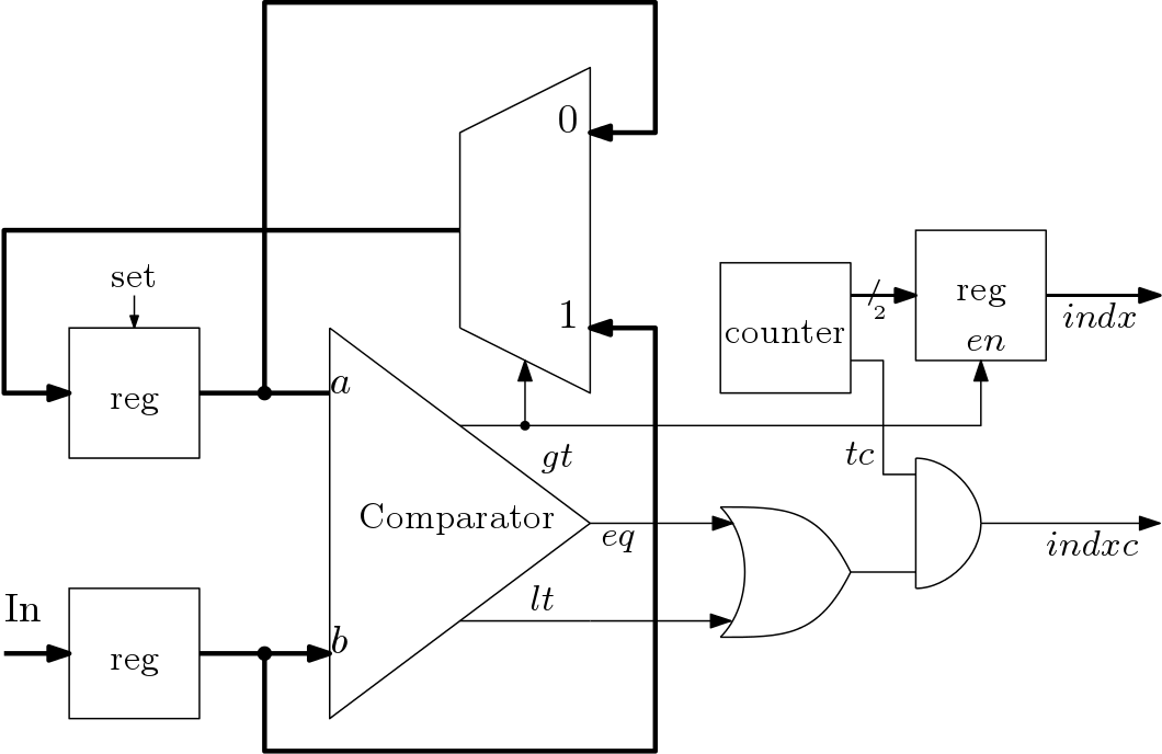
Sorting: The euclidean distances computed by the EDC block are fed to a Sorting Block (SB). The SB sorts a serial stream of data and find minimum of it. The architecture of the SB is shown in Figure 4. Initially input A of the comparator is set and the signal gt selects the input A. SB outputs the index value indx from the N for which the value of ip is minimum. Also, outputs the control signal indxc.
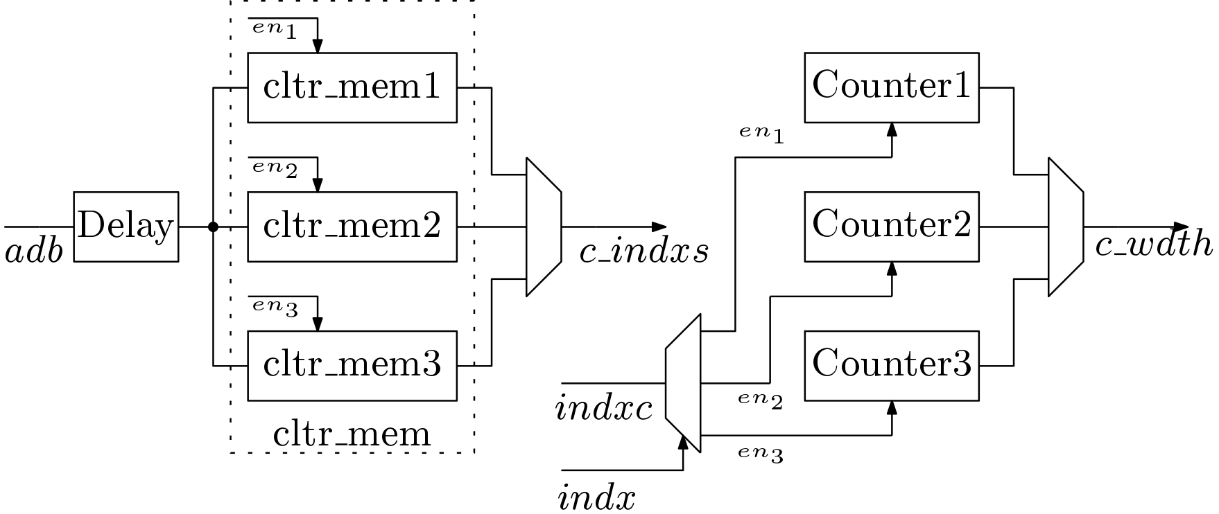
Cluster Block: The Cluster Block (CB) basically counts the number of data samples chosen in a cluster. Its architecture is shown in Figure 5. It receives indxc and indx from SB. CB generates K control signals  ,
,  ,
,  . These signals are used to increment K counters. Each counter holds the size of the respective clusters after the sorting operation. Simultaneously these control signals write the value of addresses (adb) in respective memory elements for which they are generated. Here K memory elements are used to store the indices belong to each cluster.
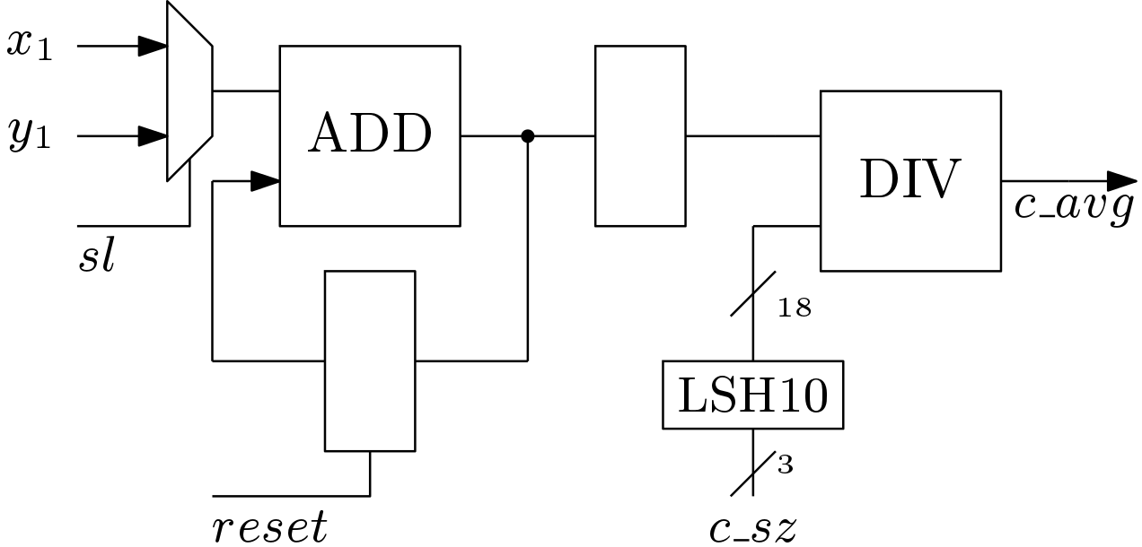
Average Block: The last step of the K-means algorithm is averaging. An Average Block (AB) is proposed here to compute the average of the elements selected in each cluster. The proposed architecture of the AB is shown in Figure 6. The averaging operation is done serially due to the high complexity involved in division operation. Here for the simple prototype, first averaging operation is done for x-elements and the for y-elements. A single divider is used here. The divider is non-restoring algorithm based radix-2 divider . The LSH10 block is 10-bit wired left shift block.
III. Design Performance Analysis
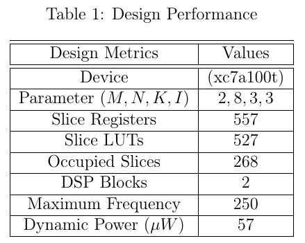
In this work, a basic prototype of K-means algorithm is implemented for parameters M = 2, N=8 and K=3. The proposed architecture implemented on NEXYS DDR2 artix7 FPGA device (xc7a100t-3csg324). Here, 18-bit fixed point data width is chosen for implementation where 10-bit is reserved for fractional part. The design performance of the proposed architecture is shown in Table 1.
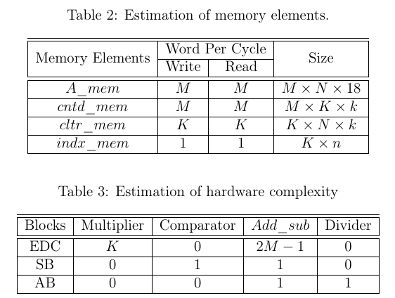
Hardware Complexity: Analysis of the hardware complexity of the proposed architecture is carried out to estimate the usage of memory elements and the major hardware blocks. The estimation of the memory blocks is shown in Table 2 and the estimation of the major hardware elements is shown in Table 3. Here k and n represents the number of bits to represent K and N respectively. This proposed architecture is designed such a way to reduce hardware resources. A single accumulation unit and a single divider block is used in this design.
Timing Complexity: In this section, the timing complexity of the proposed architecture is discussed. It is important to derive an expression to estimate the overall execution time of the architecture. Initially K clock cycles are taken to load the initial centroids to the  from . Then the euclidean distance computation starts. The total time taken to complete the euclidean distance computation stage is
  clock cycles. Here
  is the latency of the EDC block which is 3 clock cycles here. Tough the sorting operation is carried out in parallel to the euclidean computation, two clock cycles are wasted to start the next step. The next step is perform the averaging operation. The timing complexity of the averaging operation is
  clock cycles. Here
  is the latency of the divider block and the value of
  is 30. The total timing complexity for this prototype design is
  where I is the total number of iterations. Total number of clock cycles are 246 cycles for I = 3. Thus total execution time is 984
  for frequency of 250 MHz.
Click here to download the article in pdf file.
Click here to download the example of the prototype.

Verilog Code for K-means Algorithm for Clustering
K-means algorithm is very powerful for data clustering in machine learning algorithms. FPGA implementation of K-means algorithm is thus very important. This works consists of MATLAB code and detailed Verilog code for FPGA implementation of K-means algorithm.