Python productivity on Zynq (PYNQ) open-source software framework has paved the way for easy implementation of digital systems on Xilinx system on chip (SoC) devices. This project focuses on image acquisition problem in real-time image processing systems. Nowadays it is preferable to interface camera devices with FPGA boards using the inbuilt processing system (PS) provided by ARM controllers. This project solves Camera Interfacing with ZYNQ FPGA using PYNQ. A detail tutorial is provided here on
- How to make Zynq SoC boards PYNQ enabled. So that digital system implementation can be easily done using Python.
- How to interface a USB camera module for real-time image capturing.
Hardware Requirements:
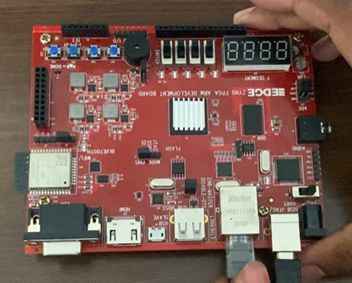
- Zynq FPGA Board (Zynq7010)
- Camera Module: [MIPI, Parallel, USB]
- Power Supply (Extra 5 V power Supply May be Required)
- JTAG/UART Cable: For debugging and programming
- Display Interface: HDMI, VGA
- Ethernet Cable
- Micro-SD Card
Software Requirements:
- Vivado Design Suite: For FPGA design
- OpenCV: Optional for advanced image processing
- Operating System: Windows/Linux
- Win32 Disk Imager
- Putty
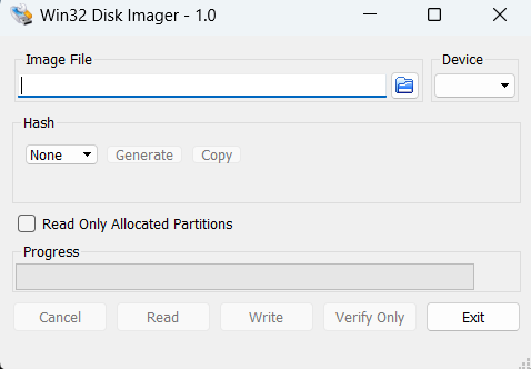
1. Download and install Win32 Disk Imager.
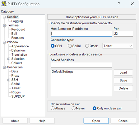
2. Download and install putty software.
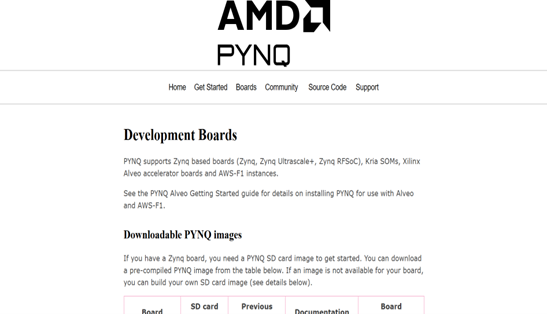
3. Open PYNQ website on Google and download the image file as per your requirement of your board, if the board which you are having is not mentioned on the website you have to create your own image file using the given instructions. (https://www.pynq.io/boards.html).
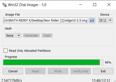
4. Open Win32 software and select the download or create image file.
5. Insert the micro-SD card reader and flash the micro-SD card and click on write. This way we are writing the image file to the SD card.
6. Now remove the micro-SD card from card reader and insert into your FPGA board.
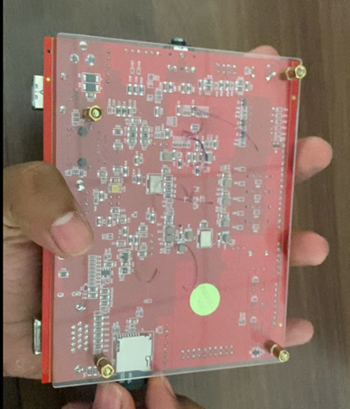
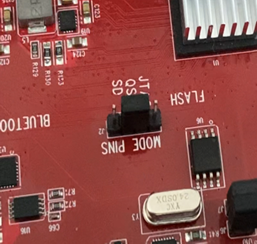
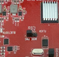
7. Set the J2 jumper or boot jumper into SD card position (short the required as shown in image). Short J2 and SD pins.
8. Turn ON the FPGA board and connect the power cable and connect the Ethernet cable for the file sharing. Ethernet cable can be connected directly to router also.
9. Connect the camera module via USB port available on the Board.
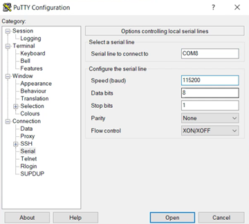
10. Open putty software and set the board rate to 115200 to view the boot screen.
11. The USB power won’t be enough for the webcam so connect 5V of external adaptor.
12. Open system settings to view board IP address.
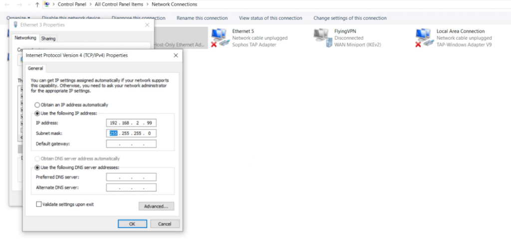
13. Assign your computer a static IP address.
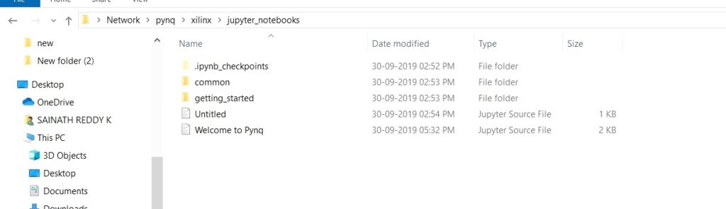
14. Open file explorer and type this \\192.168.2.99\xilinx in the navigation bar or even we can type \pynq\xilinx
15. Write username as xilinx and password also xilinx
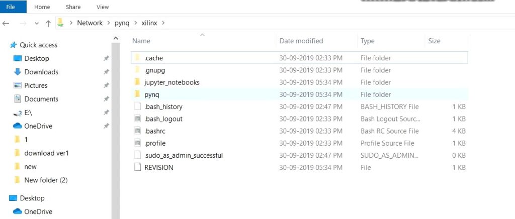
16. open the zip given and copy the pynq folder from the given zip file and copy it to the FPGA that is \pynq\xilinx and select skip all files
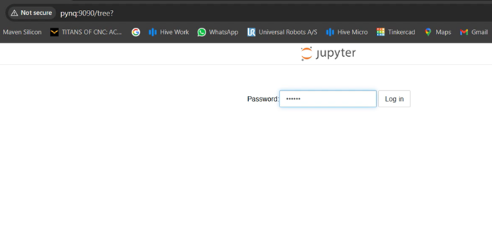
17. Open the Jupiter notebook on your Google or you can type http://192.168.2.99 to access Jupiter notebook.
18. The password will be given as xilinx for the access of the Jupiter notebook.
19. Now copy all the base files (base.bit, base.tcl, base.hdf, base.hwh) and paste in the program file location. (\pynq\xilinx\jupyter_notebooks)
20. Create a Python program for LED blinking and type the given LED code and change as per the requirement.
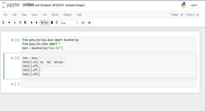
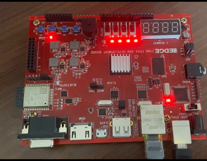
21. Observe the output on FPGA.
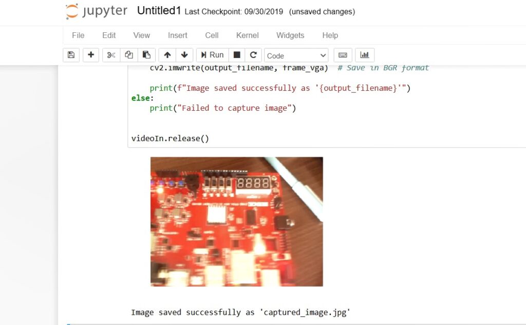
22. Now, we can do the camera interfacing by typing the given camera code.
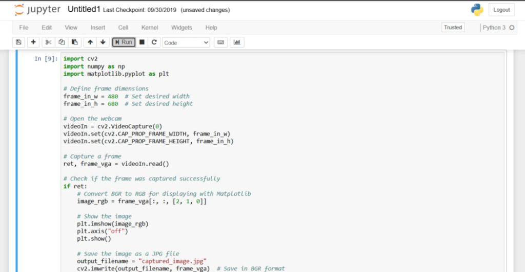
23. Make sure camera module is connected before we run the program.
24. We will the captured image in the jupyter notebook.
Click here to download the supporting project files.
Click here to download the EDGE ZYNQ board Image file.
The following students from the department of Electronics and Communication Department (ECE), School of Engineering (SoE), Dayananda Sagar University (DSU), Bengaluru, Karnataka, India have contributed for this project.
- Sainath Reddy K
- Harshith GV
- Rakshith R
- Prajwal M