Pulse Width Modulation (PWM) signal is used in place of a Digital to Analog Converter (DAC) to simplify the digital-to-analog conversion process. PWM is used when we need to generate analog voltage corresponding to some digital value. PWM is a technique where the width of a pulse is varied. This means the duty cycle of the signal is varied according to a digital value given to the PWM block. PWM signal generation is a very important topic in embedded system design where some electrical or electronic loads are controlled by digital controllers using PWM signals. In this tutorial, PWM signal generation for variable duty cycle is discussed.
In a PWM signal, the width of the pulse is varied according to a digital value (duty cycle) given to the PWM signal generator. The analog voltage is generated according to the width of the PWM signal. For example, if the duty cycle is 50 % then 1.65 V should be generated if the maximum voltage is 3.3 V. Similarly if the duty cycle is 0 then no voltage should be generated. This way width affects the generation of the analog voltage.
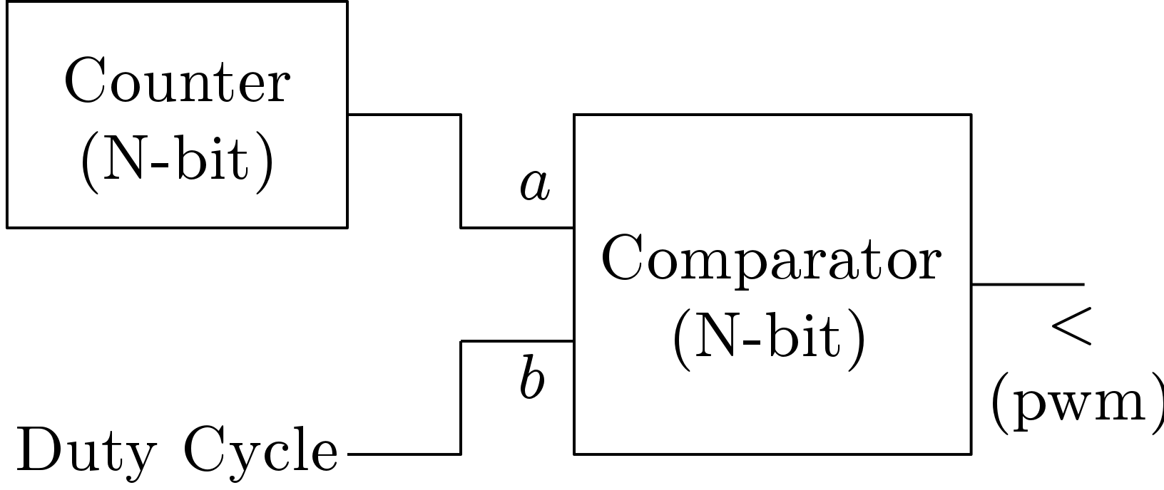
A simple architecture for generating PWM signals in FPGA is shown in Figure 1. Here, a simple N-bit loadable upcounter is used. This counter defines the frequency of the PWM signal. It counts from 0 to  and again starts from 0. The PWM signal generator block receives another input which is duty. This input and the output of the counter (count) are compared with a comparator. If count is less than duty then ‘<‘ output of the comparator gets high value and this is equal to the PWM output. The size of the comparator is same as the size of the counter. This is a very simple architecture but the only requirement is that duty input should vary with the frequency of the PWM signal
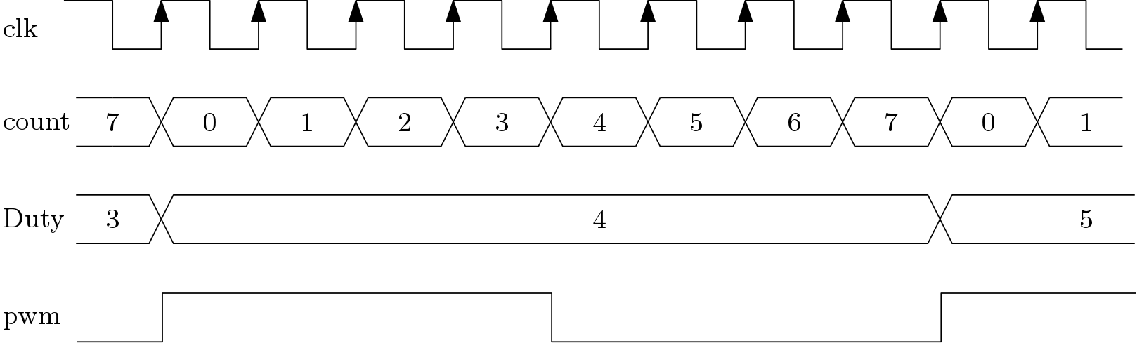
An example of the PWM signal generation is shown in Figure 2. Here the frequency of the counter is 8 clock cycles. Thus data on duty input can be changed following a gap of 8 clock cycles. In the following figure, the duty cycle of the PWM signal is 50 %. If duty input is 5 then the duty cycle will be (5/8)*100 = 62.5 %. In this example, a 3-bit counter is used for the generation of the PWM signal. Thus the input duty can take values from 0 to 255. Thus duty cycle of the PWM signal can be varied from 0 to (255/256)*100 = 99.6 %.
This basic concept will help readers to make their own architecture to generate PWM signals but if they face difficulty then can use our IP for PWM signal generation.