- Flip/flops
- Shift Registers
- PN Sequence Generator
- Counters
- Loadable Counter
- Clock Division
- Clock Division by 3
- General Approach for Clock Division
Sequential Logic Blocks
The output of sequential blocks depends on the present state as well as on past state. Sequential circuits work with a reference which is the clock. A clock signal can be of any duty cycle, any phase and of any frequency. The duty cycle of 50% is standard. In reference to the clock signal, a digital logic block can be level sensitive or edge triggered. Edge triggered flip/flops can be triggered either by a negative edge or positive edge. Dual edge triggered flip/flops also exists. More on features of the clock will be discussed in the tutorial of static timing analysis. Throughout all the tutorials flip/flops are to be realized as a positive edge triggered. A possible positive edge triggering scheme is shown below.
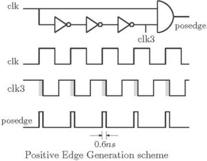
Flip/Flops:
Flip/Flops are the basic elements in every sequential circuit. Basics of flip/flops can be found in any basic digital electronic book. Here in this tutorial, Verilog implementation of flips/flops will be discussed. Flip/flops can be realized in any style of Verilog. The basic four flip/flops are realized below in different coding style.
SR flip/flop
This is the most basic flip/flop which is not directly used in any application. A SR flip/flop is realized using its behavior in behavioral style. It can be seen that the state ‘11’ is forbidden. So this code is of a NOR gate based SR flip/flop.
module srff(S,R,clk,reset,q,qb);
output reg q,qb ;
input S,R,clk,reset;
initial begin q=1'b0; qb =1'b1; end

always @ (posedge clk)
 if (reset) begin
  q <= 0;   qb <= 1;
 end
 else begin
  if (S!=R) begin
   q <= S;   qb <= R;
  end
  else if (S==1 && R==1) begin
   q <= 1'bZ;  qb <= 1'bZ;
  end
 end
endmodule
JK flip/flop
The drawbacks of SR flip/flop are eliminated in JK flip flop and thus it has no forbidden state. The excitation table can be used to write Verilog code for JK flip/flop. The Verilog code for a JK flip/flop using case statement is shown below.
module jk(q,qb,j,k,reset,clk);
output reg q,qb;
input j,k,clk,reset;
initial begin q=1'b0; qb=1'b1; end

always @ (posedge clk)
if(reset)
 begin
  q = 1'b0;  qb = 1'b1;
 end
else
 case({j,k})
  {1'b0,1'b0}: begin q=q; qb=qb; end
  {1'b0,1'b1}: begin q=1'b0; qb=1'b1; end
  {1'b1,1'b0}: begin q=1'b1; qb=1'b0; end
  {1'b1,1'b1}: begin q=~q; qb=~qb; end
 endcase
endmodule
T flip/flop
The use of T flip/flop is limited. It is used to generate control signals by changing mode of operation. T flip/flop provides easy logic optimization in designing counters. It is also used in dividing system clock.
module tff(q,reset,clk,t);

output reg q;

input t,reset,clk;

initial begin q=1'b0; end

always @ (posedge clk)

if (reset)

q <= 1'b0;

else if (t)

q= ~q;

else

q = q;

endmodule
D flip/flop
D flip/flop is the most used flip/flop in designing digital systems. D flip/flop is used either to store or to delay digital data. Realization of D flip/flop in structural and behavioral style is below.
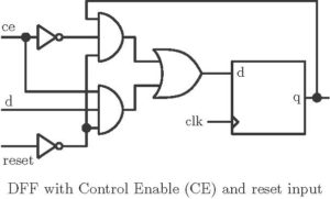
Structural Model
In structural model we have considered that D flip/flop has Control enable input (ce) along with a reset input. If ce input is high, data bit is stored in the flip/flop and if reset is high flip/flop is cleared.
module dff_struct(q,qb,d,reset,ce,clk);

output q,qb;

input d,reset,ce,clk;

wire t1,t2,d1,d2,d3;

wire clk1,clk2,clk3,posedge;

assign #0.2 clk1 = ~clk;

assign #0.2 clk2 = ~clk1;

assign #0.2 clk3 = ~clk2;

assign d1 = ~ce & q & ~reset;

assign d2 = ce & d & ~reset;

assign d3 = d1 |d2 ;

assign posedge = clk3 & clk;

assign t1 = ~(d3 & posedge) ;

assign t2 = ~(~d3 & posedge) ;

assign q = ~(t1 & qb);

assign qb = ~(t2 & q );

endmodule
Behavioral Style
module dff(q,reset,clk,d);

output reg q;

input reset,d,clk;

initial begin q=1'b0; end

always @ (posedge clk)

if (reset)

q <= 1'b0;

else

q<=d;

endmodule
Note: Flip/flops are to be designed in behavioral style as in structural style positive edge triggering is needed to be generated inside the code.
Master Slave flip/flop
Code of a master slave D flip/flop is shown below.
module msd(d,clk,reset,q);

output q ;

input d,clk,reset ;

wire q1,clkb;

assign clkb = ~clk ;

dff m1(q1,d,reset,clk);

dff m2(q,q1,reset,clkb);

endmodule
Shift Registers
There are mainly 4 types of shift registers; Serial Input Parallel Output (SIPO), Serial Input Serial Output (SISO), Parallel Input Serial Output (PISO) and Parallel Input Parallel Output (PIPO). SIPO is used to convert a serial data stream to parallel. SISO is used to shift digital data for division, multiplication, storing, frequency division etc. PISO is used in converting a parallel data stream in serial data. PIPO (simply a register), used mostly in digital circuits. PIPO is used for storing data or as a delay register. Without going into details, Verilog codes are mentioned below for these shift registers.
Parallel Input Parallel Output (PIPO)
module pipo(q,reset,clk,d);

input clk,reset;

input [3:0] d;

output [3:0] q;

dff m1(q[0],reset,clk,d[0]);

dff m2(q[1],reset,clk,d[1]);

dff m3(q[2],reset,clk,d[2]);

dff m4(q[3],reset,clk,d[3]);

endmodule
Parallel Input Serial Output (PISO)
module piso(q,reset,clk,s,d);

input clk,reset,s;

input [3:0] d;

output q;

wire t1,t2,t3,t4,t5,t6,t7;

mux_df mx1(1'b0,d[0],s,t1);

dff m1(t2,reset,clk,t1);

mux_df mx2(t2,d[1],s,t3);

dff m2(t4,reset,clk,t3);

mux_df mx3(t4,d[2],s,t5);

dff m3(t6,reset,clk,t5);

mux_df mx4(t6,d[3],s,t7);

dff m4(q,reset,clk,t7);

endmodule
Serial Input Parallel Output (SISO)
module siso(q,reset,clk,d);

input clk,reset;

input d;

output q;

wire t1,t2,t3;

dff m1(t1,reset,clk,d);

dff m2(t2,reset,clk,t1);

dff m3(t3,reset,clk,t2);

dff m4(q,reset,clk,t3);

endmodule
Serial Input Parallel Output (SIPO)
module sipo(q0,q1,q2,q3,reset,clk,d);

input clk,reset;

input d;

output q0,q1,q2,q3;

dff m1(q0,reset,clk,d);

dff m2(q1,reset,clk,q0);

dff m3(q2,reset,clk,q1);

dff m4(q3,reset,clk,q2);

endmodule
Counters
Counters can be broadly classified as follows:
- Asynchronous and Synchronous counters
- Single and multi-mode counters
- Modulus counters
- Shift Register counters.
Design of asynchronous counters (Ripple counter) is easy as flip/flops are not under control of a single clock. Its speed of operation is limited and also there may be glitches at the outputs. These drawbacks are eliminated by giving single clock reference to every flip/flops. A counter may be either an up counter or a down counter. Multimode counters are also possible which have a control input to switch between up and down. Modulus counters are defined based on the number of states they are capable of counting. Shift registers are also can be arranged to form a counter. There are two types of shift register based counter which are Ring counter and Johnson counter. A counter to count arbitrary sequence can also be designed using basic flip/flops.
In digital system design, counters may be used for different applications. Counters may be used to count a semi-arbitrary sequence or can be used to divide system clock. The start or end count also can vary in different part of a design. It is better to use a general counter for the whole design and thus loadable counter suits for this purpose. A loadable counter has a load input. If load input is high the counter takes a new initial count. Also loadable counter has a feature to stop at the desired count. It generates terminal count (tc) signal at the limit value of count.
In this Tutorial, only the loadable counter is realized in Verilog.
Loadable Counter
Behavioral Style
module ldcntup(out,data,load,en,reset,clk,tc,lmt);

output reg[3:0] out;

output reg tc;

input [3:0] data,lmt;

input load, en, clk,reset;

initial begin out=4'b00000;

tc=0; end

always @(posedge clk)

if (reset) begin

  out <= 4'b0 ;

end else if (en) begin

if (load)

  out <= data;

  else

  out <= out + 4'b0001;

end

always @(posedge clk)

if (out ==lmt)

tc<=1;

else tc<=0;

endmodule
Structural style
The block diagram of a 4-bit loadable counter is shown below.
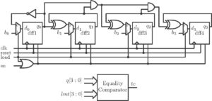
module loadcnt_up(q,b,load,en,reset,clk,tc,lmt);

input clk,load,en,reset;

input [3:0] b,lmt;

output [3:0] q;

output tc;

wire a1,a2,a3,t1,t2,t3,t4,en1;

wire [3:0] d;

assign d[0] = ~q[0];

assign d[1] = q[1]^q[0];

assign d[2] = q[2]^(q[1]&q[0]);

assign d[3] = q[3]^(q[2]&q[1]&q[0]);

mux_df m1(d[0],b[0],load,t1);

dff1 d1(q[0],clk,reset,t1,en1);

mux_df m2(d[1],b[1],load,t2);

dff1 d2(q[1],clk,reset,t2,en1);

mux_df m3(d[2],b[2],load,t3);

dff1 d3(q[2],clk,reset,t3,en1);

mux_df m4(d[3],b[3],load,t4);

dff1 d4(q[3],clk,reset,t4,en1);

assign en1 = load | en;

assign a1 = q[0] ~^ lmt[0];

assign a2 = q[1] ~^ lmt[1];

assign a3 = q[2] ~^ lmt[2];

assign a4 = q[3] ~^ lmt[3];

assign tc = a1 & a2 & a3 & a4;

endmodule
The following is the Verilog code of a 4-bit loadable down counter.
module loadcnt_dn(q,b,load,en,reset,clk,tc,lmt);

input clk,load,en;

wire [3:0] d;

input [3:0] b,lmt;

wire a1,a2,a3,t1,t2,t3,t4,en1;

output [3:0] q;

output tc;

assign d[0] = ~q[0];

assign d[1] = q[1] ^ ~q[0];

assign d[2] = q[2] ^  ( ~q[1] & ~q[0]);

assign d[3] = q[3] ^  ( ~q[2] & ~q[1] & ~q[0]);

mux_df m1(d[0],b[0],load,t1);

dff1 d1(q[0],clk,reset,t1,en1);

mux_df m2(d[1],b[1],load,t2);

dff1 d2(q[1],clk,reset,t2,en1);

mux_df m3(d[2],b[2],load,t3);

dff1 d3(q[2],clk,reset,t3,en1);

mux_df m4(d[3],b[3],load,t4);

dff1 d3(q[3],clk,reset,t4,en1);

assign en1 = load | en;

assign a1 = q[0] ~^ lmt[0];

assign a2 = q[1] ~^ lmt[1];

assign a3 = q[2] ~^ lmt[2];

assign a4 = q[3] ~^ lmt[3];

assign tc = a1 & a2 & a3 & a4;

endmodule
Equality comparator checks only the equality condition. Thus for 4-bit data width, it is made up of 4 EX-NOR gates and 1 AND gate.
Pseudo Random (PN) sequence generator
PN sequence generator is used in many applications of signal processing. PN sequence generator can be designed using Linear Feedback Shift Register (LFSR) block. A PN sequence generator for r = 4 is shown below. As, r = 4, the period of the sequence will be (24-1).
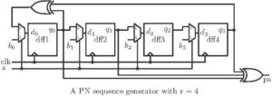
module PN_Seq_Gen(clk,reset,s,pn,d);

input clk,reset,s;

output pn;

input [3:0] d;

wire t1,t2,t3,t4,t5,t6,t7,t8,t9;

assign t1 = t3 ^ t9;

mux_df mx1(t1,d[0],s,t2);

dff m1(t3,reset,clk,t2);

mux_df mx2(t3,d[1],s,t4);

dff m2(t5,reset,clk,t4);

mux_df mx3(t5,d[2],s,t6);

dff m3(t7,reset,clk,t6);

mux_df mx4(t7,d[3],s,t8);

dff m4(t9,reset,clk,t8);

assign pn = t3^t5^t9;

endmodule
Clock Division
Other than the system clock, in many parts of the design, we need for a slower clock. Clock division can be achieved by inbuilt PLL circuitry of FPGA device. But somewhere if the inbuilt circuitry is not available, clock division is to be achieved by internal logic. In this tutorial, different clock division schemes are discussed. In all cases, output clock is to be considered having 50% duty cycle. The following diagram shows system clock with slower clocks generated from it.

Clock division approaches
There are some approaches for clock division which are discussed below. They are nearly of the same type but differ in the arrangement of the flip/flops.
Approach 1
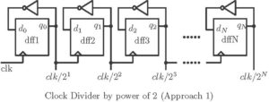
module clk_div1(clk,q0,q1,q2);

input clk;

output q0,q1,q2;

parameter reset = 1'b0;

dff m1(q0,reset,clk,~q0);

dff m2(q1,reset,q0,~q1);

dff m3(q2,reset,q1,~q2);

endmodule
Approach 2
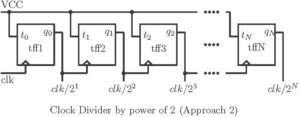
module clk_div(clk,q0,q1,q2);

input clk;

output q0,q1,q2;

parameter t = 1'b1;

parameter reset = 1'b0;

tff m1(q0,reset,clk,t);

tff m2(q1,reset,q0,t);

tff m3(q2,reset,q1,t);

endmodule
Approach 3
Modulus counter or any counter can be used to divide clock.
Clock division by a number other than the power of 2
Dividing a clock by power of two is easy. It can be achieved by any of the above approaches. Clock division by a number other than the power of 2, is a little bit tricky. Clock division by 3 is shown below.
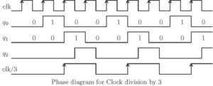
Clock division by 3
Clock division by 3 can be achieved by a mod-3 counter. A mod-3 counter can count up to 2. Clock division by 3 is explained in the following diagram.
Output q1 is shifted half clock cycle to generate q2. The final output is logical OR between q1 and q2. To divide by three, along with 2 flip/flops an extra flip is required. The block diagram is shown below.
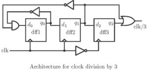
module clk_div_3(clk_out,clk,reset);

input clk,reset;

output clk_out;

wire t1,clkb,q0,q1,q2;

assign clkb = ~clk;

assign t1 = ~q0 & ~q1;

dff m1(q0,reset,clk,t1);

dff m2(q1,reset,clk,q0);

dff m3(q2,reset,clkb,q1);

assign clk_out = q2 | q1;

endmodule
A General Approach for clock division
A more general approach is required for clock division. The general circuit will divide the clock by any number. This can be achieved in the following way.
module clk_div3(clk_out,clk,reset,en);

input clk,reset,en;

output clk_out;

wire [3:0] q;

wire clkb,q4,tc;

assign clkb = ~clk;

parameter lmt = 4'b0010;

parameter data = 4'b0000;

loadcnt_up cnt(q,data,tc,en,reset,clk,tc,lmt);

dff m3(q4,reset,clkb,q[1]);

assign clk_out = q[1] | q4;

endmodule
The above code is for dividing clock by 3 using loadable counter and an extra flip/flop. Minute changes are required in this code to achieve clock division by other numbers. Mod number can be changed by changing the value of parameter lmt. For division by other numbers, only the changes to be made in the above-mentioned code are shown below.
Clock division by 5
parameter lmt = 4’b0100;//To change the mod value
//// Extra flip/flop logic…
dff m3(q4,reset,clkb,q[1]);
assign clk_out = q[2] | q4;
Clock division by 6
parameter lmt = 4’b0101;//To change the mod value
//// Extra flip/flop logic…
dff m3(q4,reset,clk,q[0]);
assign clk_out = q[1] | (q[0] & ~ q[2]);
Clock division by 7
parameter lmt = 4’b0110;//To change the mod value
//// Extra flip/flop logic…
dff m3(q4,reset,clkb,q[2]);
assign clk_out = q[2] | q4;
Clock division by 9
parameter lmt = 4’b1000;//To change the mod value
//// Extra flip/flop logic…
dff m3(q4,reset,clkb,q[2]);
assign clk_out = q[2] | q4;
More codes on clock division can be found in Verilog file of this tutorial.
Click here to download the file

This is a great site full of required data in digital system design. I had gone through once all the tutorials and find it’s very useful for the students.
Thanks bro……Please suggest any contents that i missed out.