Ultrasonic sensor is one of the most important sensors which are used for IoT applications. There are plenty of tutorials available in the internet which tells us how to interface an ultrasonic sensor with Arduino and other popular controllers. In this tutorial, we will talk about interfacing ultrasonic sensor with FPGA and for that we have used the most popular ultrasonic sensor which is HC-SR04 model and as an FPGA device we have used Spartan 6 FPGA.
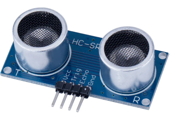
The theoretical details of this ultrasonic sensor is also available in the internet. The image of HC-SR04 ultrasonic sensor is shown in Figure 1. It has four pins, Vcc, Trig, Echo and Gnd. This sensor works fine at 3.3 V though mostly it is operated by 5 V supply. A train of pulse of width 10  s is sent to the sensor and a gap of 250 ms is maintained between the pulses. Once the sensor receive this pulse, the ultrasonic sensor sends eight 40 KHz pulses to the target. Then these pulses strikes the target and a pulse comes back to the sensor at the Echo pin. The distance is proportional to the width of this echo pulse.
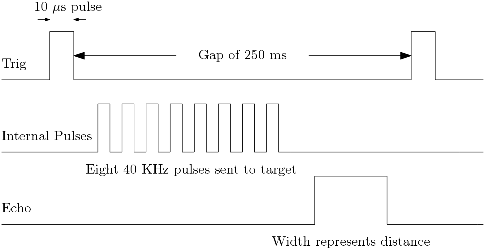
The timing diagram of the ultrasonic sensor is also shown in Figure 2. The gap between the trigger pulses should be sufficiently enough so that a gap is maintained between the echo pulse and the next trigger pulse. Here the gap between the trigger pulses is 250 ms.
In order to interface this ultrasonic sensor, a Verilog code should be written which generates the trigger pulses as shown in the above diagram. The FPGA receives the echo pulses and these pulses should increment a counter. A simple architecture to interface an ultrasonic sensor is shown Figure 3. Here, three counters are used. The first counter (cnt1) is responsible for generating the trigger pulses, second counter (cnt2) is responsible for maintaining the gap between the trigger pulses and the third counter (cnt3) is responsible for incrementing the count according to the width of the echo pulse. The function of the PG blocks is to generate enable signal for the counters. The PG block has one start input and one stop input. If a pulse is applied to the start input then an enable signal is generated and if a pulse is applied at the stop input then the enable signal is disabled.
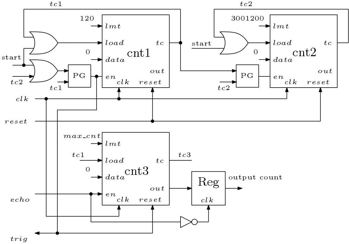
In this tutorial of interfacing ultrasonic sensor with FPGA, spartan 6 FPGA device is used which have clock frequency of 12 MHz. This means clock period is 83.3 ns. The limits of the counters are set based on this relation. For example, limit for the counter 1 is 120 to generate a trigger of period  . Similarly the case of second counter to generate gap of 250 ms. A
  pulse starts the first counter by enabling the PG block and after 10
  terminal count (
 ) pulse stops the counter 1 by stopping the first PG block. The signal then starts the second counter and the second counter generates another terminal count pulse (
 ). This pulse again starts the counter 1. This way the trigger pulses are generated and sent to the ultrasonic sensor.
The  signal is input to the FPGA and the width of this pulse is proportional to the distance of the target from the sensor. Thus this signal is used to increment the third counter. According to the width of the pulse count of the third counter will increase. The mor e the count, the more the distance. This count value is fed to a register. The signal is inverted and connected to the
  input of this register. This way the count value is stored for a cycle in that register.
In an FPGA, the distance from the target may be calculated or may not be calculated. It is not necessary to calculate the distance from the count value unless it is required. This is because distance calculation needs additional hardware. User can use the count or scaled value of the count in their application. Thus distance calculation is not included in this architecture. But in case the user wants to calculate the distance then the formula is shown below

Here,  is the distance of the target, speed of the sound is 340 m/s and
  is the delay. This delay corresponds to the width of the echo pulse and corresponds to the count value. In our case, clock period is 83.3 ns and if count value is indicated by
  then the modified formula is

The Verilog code is tested by using a seven segment decoder and the count value is scaled to accommodate on the seven segment decoder. The accuracy of distance calculation depends on the data width used for count value.
Verilog Code for Ultrasonic Sensor (3213 downloads )