- Sequence Detector using Mealy Machine
- Sequence Detector using Moore Machine
- Serial Adder
- Vending Machine
FSMs, an important category of sequential circuits, are used frequently in designing digital systems. From the daily used electronic machines to the complex digital systems, FSMs are used everywhere. For example, in a station the vending machine which dispatches ticket uses a simple FSM. In the complex digital systems the controlling part is most of the times implemented using FSMs.
FSMs are generally of two types.
- MEALY Machine: MEALY circuits are named after G. H, Mealy, one of the leading personalities in designing digital systems. The basic property of Mealy circuits is that the output is a function of the present input conditions and the present state (PS) of the circuit.
- MOORE Machine: MOORE circuits are named after E. F. Moore, another leading personality in designing digital systems. The basic property of Moore circuits is that the output is strictly a function of the present state (PS) of the circuit.
Most of the digital systems use either Moore or Mealy machine but both machines also can be used together. In initial days of digital system design when HDL languages are not discovered, Mealy or Moore machines are realized using K-Map optimization technique. The K-map optimization technique provides an optimized solution but it is a rigorous and lengthy process. On the contrary, HDL provides an easy solution to the design of FSMs by saving design time. In this tutorial, we will discuss the design of some of the digital systems using both Mealy and Moore machine. We will end up with a comparison between these two machines.
Mealy based Sequence Detector
Sequence detector is a good example to describe FSMs. It produces a pulse output whenever it detects a predefined sequence. In this tutorial, we have considered a 4-bit sequence “1010”. The first step of an FSM design is to draw the state diagram. The sequence detectors can be of two types: with overlapping and without overlapping. For example, consider the input sequence as “11010101011”. Then in ‘without overlapping’ style, the output y will be “00001000100” and the output y in ‘with overlapping’ style will be “00001010100”. The ‘with overlapping’ style also considers the overlapping sequences. The state diagram of the “1010” sequence detector using the Mealy machine in ‘without overlapping’ style is shown below.
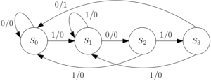
Figure 1: Mealy based ‘1010’ sequence detector without overlapping.
The drawing of the correct state diagram is very crucial in designing FSMs. Though there is no fixed rule of drawing state diagrams some comments can be made. In present state S0, if the input is ‘1’ then the next state is S1 and if input ‘0’ then the next state is the current state. It is similar for present state S1. In present state S2 if there is a false bit, the next state is S0 and in present state S3 if there is a false bit, the next state is S1. From the above statement it can be said that if there is a false input, the next state will be the nearest similar state. It is to remember that for any combinations we have to reach the branch where the output is ‘1’. For example, consider input sequence (din) as “011010”. The sequence of next states will be “S0S1S1S2S3S0”.
The ‘1010’ sequence detector using the Mealy machine without overlapping is realized using Verilog. The Verilog code is given below.
module melfsm(din, reset, clk, y);

input din;

input clk;

input reset;

output reg y;

reg [1:0] cst, nst;

parameter S0 = 2'b00, //all states

          S1 = 2'b01,

          S2 = 2'b10,

          S3 = 2'b11;

always @(cst or din)  /// use posedge clk to avoid glitch

 begin

 case (cst)

   S0: if (din == 1'b1)

          begin

         nst = S1;

          y=1'b0;

          end

      else

          begin

          nst = cst;

          y=1'b0;

          end

   S1: if (din == 1'b0)

          begin

        nst = S2;

          y=1'b0;

          end

       else

          begin

          y=1'b0;

           nst = cst;

          end

   S2: if (din == 1'b1)

          begin

         nst = S3;

          y=1'b0;

          end

          else

          begin

          nst = S0;

          y=1'b0;

          end

   S3: if (din == 1'b0)

          begin

         nst = S0;

          y=1'b1;

          end

       else

          begin

          nst = S1;

          y=1'b0;

          end

   default: nst = S0;

  endcase

end

always@(posedge clk)

          begin

           if (reset)

             cst <= S0;

           else

             cst <= nst;

          end

endmodule
The optimized logic architecture for ‘1010’ sequence detector without overlapping using Mealy Machine is shown below. Here instead of giving the RTL schematic, we have given the K-map optimized block diagram for better understanding.
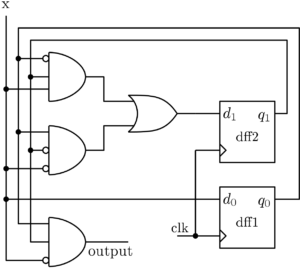
Figure 2: ‘1010’ sequence detector without overlapping using the Mealy machine
Sequence detector with overlapping
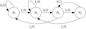
Figure 3: State diagram for ‘1010’ sequence detector using the Mealy machine (with overlapping)
The Verilog implementation of this FSM can be found in Verilog file in the download section.
Moore based sequence detector
The same ‘1010’ sequence detector is designed also in Moore machine to show the differences. The state diagrams for ‘1010’ sequence detector with overlapping and without overlapping are shown below.
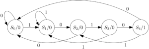
Figure 4: State diagram for ‘1010’ sequence detector using Moore machine (without overlapping)
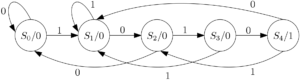
Figure 5: State diagram for ‘1010’ sequence detector using Moore machine (with overlapping)
The Moore machine can be designed same way as Mealy machine using Verilog. The only difference is that in case of Moore machine there are 5 states. Instead of output branch, there is an output state in case of Moore Machine. The objective is to reach the output state from any state. The Verilog codes for Moore implementations can be found in Verilog file in Download section. The logic diagram is shown below for ‘1010’ sequence detector without overlapping.
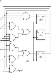
Figure 5: Block diagram for ‘1010’ sequence detector using Moore machine (without overlapping)
A comparison can be drawn between Figure 3 and Figure 5. In Figure 3, which is the block diagram, of a Mealy machine, output depends on input and the current states or output of the flip-flops. Whereas in Figure 5, which is the block diagram of a Moore machine, output is function of only the present states or output of the flip-flops. And also there is an extra flip-flop used in case of Moore Machine.
Go to the Top
Serial Adder:
Serial adder design using FSM is a popular design which is frequently used in literature. Here in this tutorial, we will design a serial adder using the Mealy machine. The state diagram for the serial full adder is shown below. There are two states defined based on carry. The state S0 is for carry equal to zero and S1 is for carry equal to 1.
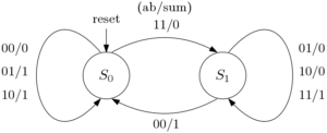
Figure 6: State diagram for serial full adder
The state diagram can be understood clearly from the truth table of full adder which is shown below.
Table 1: Truth table for full adder
| PS | cin | a | b | sum | cout | NS |
| S0 | 0 | 0 | 0 | 0 | 0 | S0 |
| S0 | 0 | 0 | 1 | 1 | 0 | S0 |
| S0 | 0 | 1 | 0 | 1 | 0 | S0 |
| S0 | 0 | 1 | 1 | 0 | 1 | S1 |
| S1 | 1 | 0 | 1 | 0 | 1 | S1 |
| S1 | 1 | 1 | 0 | 0 | 1 | S1 |
| S1 | 1 | 1 | 1 | 1 | 1 | S1 |
| S1 | 1 | 0 | 0 | 1 | 0 | S0 |
module serial_add(a,b,cin,reset,clk,sum,nst);

output reg sum;

input a,b,cin;

input clk;

input reset;

reg cst;

output reg nst; /// carry out

initial begin cst = cin; end

/// state assignment

parameter S0 = 1'b0,

          S1 = 1'b1;

/// Synvhronous with clock

always @(posedge clk)

 begin

 case (cst)

S0 : begin

            sum=a^b;

            if(a&b)

   nst = S1;

            else nst = cst;

   end

S0 : begin

            sum=~(a^b);

            if(~a&~b)

   nst = S0;

            else nst = cst;

   end

default: nst = S0;

endcase

end

/// reset facility

always@(posedge clk)

begin

 if (reset)

   cst <= S0;

 else

   cst <= nst;

end

endmodule
Vending Machine Problem
Vending Machine is a practical example where FSM is used. The ticket dispatcher unit at the stations, the can drinks dispatcher at the shops are some examples of Vending machines. Here in this tutorial we will try to understand a simple Vending machine which dispatches a can of coke after deposition of 15 rupees. The machine has only one hole to receive coins that means customers can deposit one coin at a time. Also the machine receives only 10 (T) or 5 (F) rupee coin and it doesn’t give any change. So the input din can take values like
- din = 00, no coin deposited.
- din = 01, 5 rupee coin (F) deposited.
- din = 10, 5 rupee coin (T) deposited.
- din = 11, forbidden – Both coin can’t be deposited at same time.
Also a customer can deposit 15 rupees by the following ways
- 10 + 5 = 15
- 5 + 10 = 15
- 5 + 5 + 5 = 15
If more money is deposited than 15 then the machine will be on the same state asking the customer to deposit right amount. The state diagram for the vending machine is shown below.
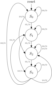
Figure 7: The state diagram for the Vending machine
The PS/NS and output table for the Vending machine problem discussed above is shown below.
Table 2: PS/NS and output
| Present State |
Next State | Output | ||||
| din = 00 | din = 01 | din = 10 | din = 00 | din = 01 | din = 10 | |
| S0 | S0 | S1 | S2 | 0 | 0 | 0 |
| S1 | S1 | S2 | S3 | 0 | 0 | 1 |
| S2 | S2 | S3 | S2 | 0 | 1 | 0 |
| S3 | S3 | S1 | S2 | 0 | 0 | 0 |
module vending(T,F,reset,clk,y);

output reg y;

input T,F;

input clk;

input reset;

wire [1:0] din;

assign din = {T,F};

reg [2:0] cst, nst;

parameter S0 = 2'b00,

          S1 = 2'b01,

          S2 = 2'b10,

          S3 = 2'b11;

always @(posedge clk or din)

 begin

 case (cst)

 S0: if (din == 2'b00)

          begin

         nst = S0;

          y=1'b0;

          end

      else if (din == 2'b01)

          begin

          nst = S1;

          y=1'b0;

          end

      else if (din == 2'b10)

          begin

          nst = S2;

          y=1'b0;

          end

 S1: if (din == 2'b00)

          begin

         nst = S1;

          y=1'b0;

          end

      else if (din == 2'b01)

          begin

          nst = S2;

          y=1'b0;

          end

      else if (din == 2'b10)

          begin

          nst = S3;

          y=1'b1;

          end

 S2: if (din == 2'b00)

          begin

         nst = S2;

          y=1'b0;

          end

      else if (din == 2'b01)

          begin

          nst = S3;

          y=1'b1;

          end

     else if (din == 2'b10)

          begin

          nst = S2;

          y=1'b0;

          end

S3:  if (din == 2'b00)

          begin

         nst = cst;

          y=1'b0;

          end

      else if (din == 2'b01)

          begin

          nst = S1;

          y=1'b0;

          end

      else if (din == 2'b10)

          begin

          nst = S2;

          y=1'b0;

          end

   default: nst = S0;

  endcase

end

always@(posedge clk)

begin

 if (reset)

   cst <= S0;

 else

   cst <= nst;

end

endmodule
Comparison between Moore and Mealy Machine
| Mealy Machine | Moore Machine |
| Output depends on present input and present state of the circuit. | Output depends only on the present state of the circuit. |
| Required less number of states | Required more number of states than Mealy machine |
| Asynchronous output generation though the state changes synchronous to the clock | Both output and state change synchronous to the clock edge |
| Faster, the output is generated on the same clock cycle. | The output is generally produced in the next clock cycle |
| Glitches can be generated as output change depends on input transition. | Safer to use, because they change states on the clock edge |
Note: To avoid the glitches in the Mealy machine, registered Mealy machine or synchronous Mealy or really Moore is used. Synchronous Mealy machines are nothing but a Moore machine without output state decoder.
Click here to download the file
This is a very good tutorial on FSM design. This will definitely help the beginners.
still good for beginners…..Then i have to try it for experts now.
Thanks for the mɑrvelous posting! I truly enjoyed reading
it, you’re a great author. I will make certain to bookmark your blߋg аnd will сome back at ѕome point.
І want to encourage you to continue your great writіng,
havе a nice day!
I was reading some of your content on this website and I think this internet site is real instructive! Retain putting up.