In the previous tutorials, we have discussed about the fixed point architectures. Majority of FPGA based architectures are fixed point based. In the fixed point architectures, the number of bits reserved for integer and fractional part is fixed. Thus there is a limitation in representing wide range of numbers. This limitation results truncation error at the output. Accuracy can be increased by increasing the word length but this in turn increases hardware complexity. At some point further increase in word length can not be tolerable. The floating point representation solves this problem.
Previously we have discussed about basics of floating point numbers in Digital System Design Basics. The usage of floating point representation in real time implementations is limited. The reason behind this fact is that implementation of floating point architectures is complex. Due to higher complexity, floating point architectures are not suitable for rapid prototyping. On the other hand, floating point architectures provides better accuracy than fixed point architectures.
Floating Point Data Format
The objective of this tutorial is to discuss the basics of floating point representation and the basic architectures for floating point arithmetic operation. According to IEEE 754 standard there are two data formats for floating point numbers, viz, single precision (32-bits) and double precision (64-bits). But here we will design the architectures for 16-bit to achieve moderate accuracy and lower resources. A floating point number can be represented in binary as
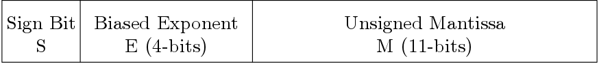
So, a floating point number has three fields, viz, sign field (  ), exponent field (
  ) and mantissa (
  ). The exponent field is a added to a bias component too differentiate between negative and positive exponents. The decimal equivalent of this representation is

Here the exponent is of 4-bits thus bias is  . The range of the exponent is thus 0 to 15 (Neglecting the infinity which is not required).
Example: Convert  in floating point representation.

Here the bit which is shown in bold is the hidden bit.
Maximum number that can be represented is

Minimum number that can be represented is

Both the numbers also can be negative. The minimum number is not normalized here thus it is actually minimum subnormal number. If normalized then the minimum number will be

Zero is represented as
 or
or 
Floating Point architectures
All the floating point architectures designed here follows 16-bit data width. These architectures are designed without optimization for simple understanding of floating point arithmetic. Here architectures are designed to support normal numbers but can support subnormal numbers also. Following architectures are discussed to perform different arithmetic operations
- Fixed Point to Floating Point Conversion
- Leading Zero Counter
- Floating Point Addition and Subtraction
- Floating Point Multiplication
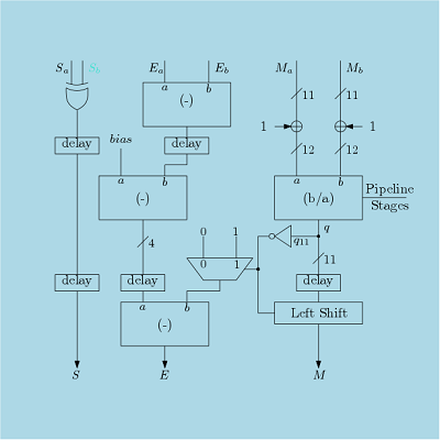
- Floating Point Division
- Floating Point Square Root
- Floating Point Comparison
- Floating Point to Fixed Point Conversion
Thus in this tutorial, all the major floating point architectures are discussed and implemented using Verilog structural coding. We have avoided the rounding here as it adds more hardware and also it can be considered in fixed point.
Verilog Codes for Floating Point Arithmetic Blocks
Here, different floating point arithmetic blocks are designed using Verilog HDL. These blocks are
- Floating Point Adder/Subtractor
- Floating Point Multiplier
- Floating Point Divider
- Floating Point Square Root
- Floating Point Comparison
- Conversion Between Fixed Point and Floating Point.
- Leading Zero Counter
Verilog code for all the blocks are provided here. All the blocks are designed using 16-bit word length, instead of standard single and double precision format, so that a designer can customize a block as per his/her own requirement.