Contents for fast addition are
- Carry Look Ahead Adder
- Parallel Prefix Adder trees
- Carry Skip Adder
- Carry Increment Adder
- Carry Select Adders
- Carry Save Addition
- BCD Addition
Addition and subtraction can be performed using the same logic block in two’s complement binary representation. The controlled adder/subtractor logic block is discussed in the tutorial of combinational circuits. In this tutorial, we will discuss various techniques available to perform the fast addition operation. Adders are the most important basic logic element in designing a digital system. So, it is important to optimize the performance of this logic block. There are various techniques discovered to make faster adder, to design adders with low power consumption or to design such an adder which is comparatively faster but area efficient. Application specific tradeoffs are to be considered. This is our first tutorial towards logic design for computer arithmetic. The basic idea about various types of adders is discussed here. For the detailed analysis of delay, timing analysis and cost, readers should go through various textbooks on computer arithmetic.
Ripple Carry Adder (RCA)
We will not discuss the RCA here as it is discussed in the tutorial of combinational circuits. But it is used in implementing other adders.
Carry Look Ahead Adder
Table 1: Truth table of full adder
| ROW | A | B | Cin | S | Cout |
| 1 | 0 | 0 | 0 | 0 | 0 |
| 2 | 0 | 0 | 1 | 1 | 0 |
| 3 | 0 | 1 | 0 | 1 | 0 |
| 4 | 0 | 1 | 1 | 0 | 1 |
| 5 | 1 | 0 | 0 | 1 | 0 |
| 6 | 1 | 0 | 1 | 0 | 1 |
| 7 | 1 | 1 | 0 | 0 | 1 |
| 8 | 1 | 1 | 1 | 1 | 1 |
From the truth table of the full adder, some conclusions can be made. In the first two rows output carry ( ) is always zero. In the rows from 3 to 6, input carry (
 ) propagates to output carry. And in the last two rows, is one. These are the conditions for output carry. The general Boolean expression for the output carry can be written in the following style.


An alternate equation of propagated carry is

Both the equations can be used. The first equation is hardware efficient but the second equation is more popular as only a ‘OR ’ gate is required. The use of the second equation will be discussed later. Until now stick to the first one.
The variable  represents the generated carry and
  is the propagation condition. In the rows from 3 to 6, when
  is true is equal to . Here i = 0, 1… (n-1), where n is data width. Initially
  is equal to . Then the equation for sum (S) is

The architecture for the 4-bit CLA is given below.
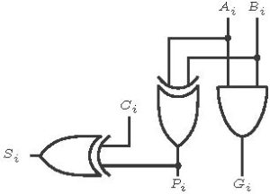
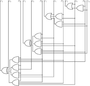
Figure 1: 4-bit CLA
Click here to download the Verilog file.
Higher bit adders using CLA
Carry look ahead adders proves to be very fast regardless of the data width. It takes  delay to compute sum of numbers of any width where
  is the delay of a single gate. But for higher data width the hardware complexity to generate carry is extremely high and thus area increases. To reduce the hardware overhead, several techniques are proposed to efficiently design the carry generation block for higher order adders. Higher order adders can be implemented in terms of smaller adders. Like a 64-bit adder can be implemented using 16 numbers of 4-bit adders. Generally, 4-bit adders are taken as the basic building block.
In a 4-bit adder, 4-bits are group together and so the corresponding signals can also be grouped. The equations for block propagated carry, block generated carry and carryout are given below.
 for
for 
 for
for 
 for
for
 for
for

First consider an 8-bit adder is to be implemented using CLA. It can be designed using two 4-bit adders.
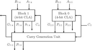
Figure 2: 8-bit adder using CLA
Click here to download the Verilog file.
Go to the Top
The carry Generation Unit in the Carry look adders is the most critical. Several tree based designs are available in literature for the carry generation unit. The tree based designs are implemented using parallel prefix circuit. A prefix circuit receives inputs  ,
,  ,…,
,…,  and generates outputs like ,
  ,….
,…. ….
…. where
where  is symbol for binary associative operation. Carry look ahead adders with prefix circuit are sometimes called as prefix adders. To understand the prefix tree adders a new associative binary function is defined.

For n=4, associative operation will be

Prefix Tree Adders
Some of the popular prefix adders are discussed in this tutorial. In the figures, the empty circles represents the block which generates the individual propagate and generate conditions and the bullets represents the block which performs the associative binary operation which is discussed above.
Brent-Kung Parallel Prefix Tree-
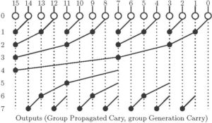
Figure 3: Brent-Kung Parallel Prefix Tree
Click here to download the Verilog file.
- Total stages –
 (Higher Depth and so delay is higher)
 - Fan out = 2 at each stage, avoids explosion of wires, Odd computation
Ladner-Fischer Adder
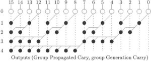
Figure 4: Ladner-Fischer Parallel Prefix Tree
- Stages –
 (Low depth).
 - Total nodes =

- Nodes are having high fan-out.
Kogge-Stone Adder
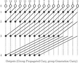
Figure 5: Kogge -Stone Adder
- Stages – (Low depth).
- Total Nodes =
 (Higher Area, Long Wires)
 - Fan out is minimum – 2 at each stage. (Faster Performance)
Han-Carlson Adder
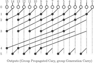
Figure 6: Han-Carlson Adder
- Stages –
 (Moderate Stage)
 - Hybrid Adder, 1st stage Kogge-Stone and 2nd stage is Brent-kung adder.
- Efficient and suitable for VLSI implementation.
Manchester Carry Chain Module (MCC)
The Manchester carry chain is a variation of the carry-lookahead adder that uses shared logic to lower the transistor count. A Manchester carry chain generates the intermediate carries by tapping off nodes in the gate that calculates the most significant carry value. However, not all logic families have these internal nodes, CMOS being a major example. Dynamic logic can support shared logic, as can transmission gate logic. One of the major drawbacks of the Manchester carry chain is that the capacitive load of all of these outputs, together with the resistance of the transistors causes the propagation delay to increase much more quickly than a regular carry lookahead. A Manchester-carry-chain section generally doesn’t exceed 4 bits. The Manchester carry scheme for the group of 4 is shown below.
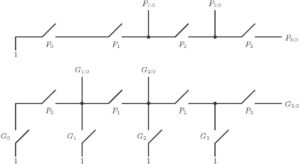
Figure 7: Manchester Carry Chain Scheme
Carry Skip Adder
The Sarry Skip Adder, also known as carry bypass adder, based on the similar carry propagation criteria. If the propagation criterion is satisfied, the input carry is passed to the output. Thus the status of output carry is evaluated using propagation criteria. The simple carry skip adder for n=8 is shown in figure 8. The performance of the carry skip adder scheme depends on the size of carry skip adder block size. Here 8-bit adder is implemented using the block size of 4-bit. The condition for the block size is  . The variable block size is adopted to achieve fast addition.
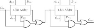
Figure: 8-bit Carry Skip Adder
Click here to download the Verilog file.
Go to the Top
Carry Increment Adder
The design of Carry Increment Adder (CIA) consists of an adder block (CLA, RCA) and an incremental circuitry. The incremental circuit can be designed using HA’s in ripple carry chain with a sequential order. For example, the addition operation for 8-bit data can be done by dividing the total number of bits in two groups of 4bits and addition operation is done using 4bit RCA or CLA. This fast addition technique is not much popular since a carry chain still exists. The architecture of CIA is shown in figure 9.
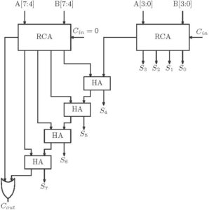
Figure 9: Carry Increment Adder
Click here to download the Verilog file.
Go to the Top
Carry Select Adder
The carry select adder consists of two addition paths. One path calculates sum considering carry in is equal to zero and the other path calculates sum with carry in is equal to one. After the sum is calculated, correct sum and correct carry out is selected through a mux. Thus it has two adder blocks and two mux units. The adder block can be an RCA or a CLA. The size of the carry select block can be fixed or can be variable. For fixed-size carry select adder, optimum delay occurs when block size is  . For example, the block size is 4 for n = 16. So, there will be two 4-bit RCA/CLA in a carry select adder block. Thus carry select adders achieve fast addition by consuming more hardware. The simple block diagram of a carry select adder is shown in figure 10.
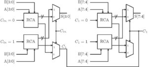
Figure 10: 8-bit Carry Select Adder
Click here to download the Verilog file.
If the block size is fixed then carry select adder is called linear. For example, a 16-bit adder can be realized using block sizes 4-4-4-4. On the other hand to improve the performance non-linear carry select adders choose variable block sizes. For example, the same 16-bit adder can be implemented by block sizes 2-2-3-4-5.
Conditional Sum Adder
The idea of carry select adder is behind the idea of fast conditional sum adders. An n-bit adder can be designed using smaller n/2 or n/4 bit adders using the same carry select concept. For example, a 4-bit adder can be built using seven 1-bit adders. This example is shown in figure 11.
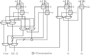
Figure 11: 4-bit Conditional Sum Adder
Click here to download the Verilog file.
Ling Adders
Ling adders are variations of carry-look ahead adders. It uses the simpler equation of group generated carry and thus resulting fast addition. The equation for the output carry of a 4-bit adder block can be expressed as

Assume,  or
or  . The equation of group generated carry in a block of 4-bit adder is

Assume As,  ,
,  . So, in the above equation
  can be taken as common factor and the equation be re-written as

Where  can be written as

And

The general expression is

The sum is calculated by the following equation


The calculation of  is faster than calculation of which reduces the delay in calculating sum.
Hybrid Adders
A hybrid adder is which uses two or more above kind of Addition techniques to implement higher order adder. Generally, a hybrid adder employs one kind of adder for generating the carry and another kind for computing sum. For example, Manchester Carry Chain (MCC) can be used for Carry generation and Carry select Adder can be used for sum calculation.
Multi operand addition
Carry Save addition
Up to now, we have discussed fast addition with two operands. If several operands are to be added then these adders are needed to be used several times. Direct application of the adders is in the multiplication process where several operands are to be added. Carry save addition is one such technique which reduces the complexity involved in multi-operand addition.
Carry Save Adder (CSA) is actually a three input adder which receives three operands and produces two outputs. For 1-bit data, CSA is actually a full adder. It sometimes called as a 3:2 counter as it compresses three inputs to two outputs. The general equation for a CSA is given below

Where s and c are the sum and carry outputs from CSA. They are evaluated as
 and
and 
A simple CSA based addition of three operands is shown below. Here we need one stage CSA and one Carry Propagated Adder (CPA).
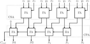
Figure 12: Carry Save Adder for 3 operand addition
Click here to download the Verilog file.
Tree of Carry Save Adders
For fast addition of multi operands tree of CSAs can be formed. An example of the addition of seven 8-bit operands is shown below. The scheme mentioned below to add seven operands is popularly known as Wallace Tree. Five CSA modules and one CPA module are used here.
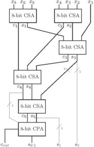
Figure 13: 7 operands addition using CSA
Click here to download the Verilog file.
The scheme of the fast addition of multiple operands is needed to be understood. A basic scheme of the addition of 7 four bit numbers is shown below using Wallace tree addition method.
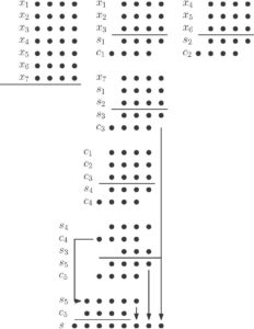
Figure 13: Scheme for the addition of 7 operands
There are other type CSA trees are available for multi-operand addition. We will discuss them in more detail in the tutorial for multiplication.
BCD addition
Though BCD addition does not belong to the category of fast addition, we discussed it here as it is also a type of adder. In BCD addition inputs are in BCD format and the output is also in BCD format. In BCD format, counting is done from 0 to 9. If the summation result is greater than 9, then correction is needed. And that correction is done by adding 6 to the summation result. The equation for the correction logic is

Here  is the carryout of the last adder in the first stage. The logic diagram is shown below in figure 3.
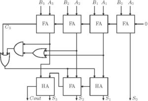
Figure 14: 4-bit BCD Adder
Click here to download the Verilog file.
Conclusion
We have discussed several techniques for fast addition in this tutorial but a proper comparison not shown. So that the general question arises that which adder is suitable for system design? For two operands Carry Lookahead Adder performs well. For higher data width, CLA with prefix adders is a common choice. In signal processing, vector multiplication is a common operation to be performed and it involves multipliers and several multi-operand additions. Carry save adders are always suitable for these type of multi-operand addition. We will discuss further multi-operand addition techniques in the tutorial for multiplication.
Click here to download the document
This is a very nice post. I have gone through the whole post. I am expecting further posts.
HI sir, This is a great post. I expecting further posts from you.