Contents for Digital System Design Basics are:-
- Design Approaches
- Design Methodologies
- Binary Number System
- Fixed Point Format
- Floating Point Format
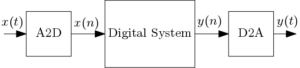
A system which receives digital inputs and produces digital outputs can be implemented on digital hardware. A digital filter is an example of such system. A digital version of an analog signal is input to the digital filter and the filtered output is also digital. Example of other systems is signal domain transformers (FFT, Wavelet, Curvelet, DCT etc), signal processing or image processing algorithms, data compression systems, video processors etc. Digital systems are placed between analog to digital converters (A2D) and digital to analog converters (D2A) which is can be explained by the following diagram.
Digital System Design Approaches
A top-down approach (a divide and conquer approach) is basically the breaking down of a system to gain insight into its compositional sub-systems in a reverse engineering fashion.
A bottom-up approach aims at realizing the desired complex design by suitably selecting subblocks from a given set of subblocks and setting up interactions among them.
A mixed design approach uses both the above-mentioned approaches and mostly used to realize complex designs.
Design Methodologies
The various VLSI design methodologies are :
- Full Custom – In a full custom design, specifications are given for each individual transistor and for their connections. Performance for a full custom design is better than all other design methodologies and the area is But design time is very high.
- Semi-Custom – An alternative solution is to use small transistor level sub-circuits repeatedly or to use standard cells libraries. Whereas standard cells are designed in full custom design methodology. Performance is compromised but design time is lesser than that of full custom design.
- Gate Array – Gate array-based design is most popular in implementing complex systems. Designs are implemented in terms of programmable logic blocks and programmable interconnect. Performance is compromised, speed is lesser than both semi-custom and full custom design but a prototype of a complex design can be made in very short time.
Basics of Digital Electronics
In designing a complex digital system, basic knowledge of digital electronics is required most. Digital gates are the basic building blocks in designing a complex digital system. It is not possible to discuss the digital electronics course here. It will be assumed that readers have a very good knowledge of basic digital gates, Boolean algebra, logic optimization techniques, combinational circuits and sequential circuits. Otherwise given references can be useful.
Binary Number System:-
In the digital system, a signed number is represented in various ways which are
Sign and magnitude – In this representation, one bit (MSB) is allocated to represent a sign of a number. When this bit is zero, the number is positive and for negative numbers, this bit is one. The range of signed and magnitude representation is −2N−1 to 2N−1
Ones’ Complement – The ones’ complement of a binary number is defined as the value obtained by inverting all the bits in the binary representation of the number. The range of ones’ complement number system for the bit length of N is − (2N−1−1) to 2N−1−1. It has different representations for plus zero and minus zero.
Two’s Complement – The two’s complement number system is most used to represent signed numbers as mathematical operations are identical to those of unsigned binary numbers. First ones’ complement of a number is found then one is added to find two’ complement. The range of two’s complement number system is −2N−1 to 2N−1−1. It has a single representation of zero.
Two’s Complement Arithmetic Operations:-
Addition and Subtraction
In two’ s complement number system, numbers can be treated as unsigned numbers as addition and subtraction operations are identical.
| Unsigned | Two’s complement | |||||||
| A | 1 | 1 | 1 | 1 | 15 | -1 | ||
| B | + | 0 | 1 | 1 | 1 | 7 | 7 | |
| 1 | 0 | 1 | 1 | 0 | 22 | 6 |
The overflow carry is neglected. The subtraction operation similar to the addition operation where overflow borrow out is neglected. The more general way of doing subtraction is
| Unsigned | Two’s complement | |||||||
| A | 1 | 1 | 1 | 1 | 15 | -1 | ||
| B | – | 0 | 1 | 1 | 1 | 7 | 7 | |
| 1 | 0 | 0 | 0 | 8 | 8 |
| Subtraction by addition | ||||||||
| Unsigned | Two’s complement | |||||||
| A | 1 | 1 | 1 | 1 | 15 | -1 | ||
| Two’s complement of B | + | 1 | 0 | 0 | 1 | 7 | 7 | |
| 1 | 1 | 0 | 0 | 0 | 8 | 8 | ||
Multiplication
Multiplication of two numbers can be done in the following manner
| Unsigned | Two’s complement | |||||||||
| A | 1 | 1 | 1 | 1 | 15 | -1 | ||||
| B | x | 0 | 1 | 1 | 1 | 7 | 7 | |||
| 0 | 0 | 0 | 0 | 1 | 1 | 1 | 1 | 8 | 8 | |
| 0 | 0 | 0 | 1 | 1 | 1 | 1 | 0 | |||
| 0 | 0 | 1 | 1 | 1 | 1 | 0 | 0 | |||
| 0 | 0 | 0 | 0 | 0 | 0 | 0 | 0 | |||
| 0 | 1 | 1 | 0 | 1 | 0 | 0 | 1 | 9 | -7 |
As the numbers are of 4-bit length, at the output 4-bits from the LSB are taken. If the result is negative, two’s complement is taken. One way is to take two’s complement of the input numbers before multiplication, so that result will be always positive.The multiplication result depends on the data precision taken for certain data length. Details on the precision of data will be discussed in the next section.
Data Representation:-
Fixed point data representation
In fixed-point data representation, data width is fixed. For a particular design, data width can be of length 4, 8, 16, 18, 24 or 32. Precision can be varied to represent the fractional part as per accuracy. Higher the word length, higher will be the accuracy. Fixed point data representation along with two’s complement arithmetic is mostly used in the practical digital circuits for its easy implementation. An example of this data representation is given below.
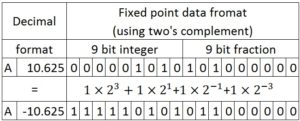
In this tutorial, we will use fixed-point data format and two’s complement data representation. 18-bit data width will be used with 9 bits for fraction part.
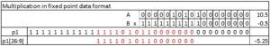
An example of multiplication in the fixed-point data format is shown below. Inputs A and B has 18 bit data length and full precision output (p1) length will be of 36 bit. Output with 18 bit precision highlighted.
Floating point data representation
Floating point data representation is used in systems where better accuracy is required. Very large number or a very small number can be represented using floating point representation. The general format for floating point numbers is

Where significand (mantissa) is an integer, the base is 2 for a binary system and the exponent is also an integer. There is no unique representation in floating point data representation. Normalized representation is mostly used. For normalized numbers range of mantissa is 1 ≤ mantissa < base.
The standard format for floating point data representation for a data width of 8 bit is
|
sign (1 bit) |
Biased Exponent (4 bits) |
Mantissa (3 bits) |
A biased exponent uses some value other than 0 as a baseline, which must be subtracted to get the actual exponent value. As 4 bits are reserved for the exponent, 7 is used as a baseline.
Standard formats to represent Floating point numbers
- 32 – bit format (single precision)
- 64 – bit format (double precision)
- 80 – bit format (extended precision)
Example: Decimal to floating point representation (-86)
- Convert decimal to binary: (-1010110)
- Then convert this to binary scientific notation: (−1.010110 × 26)
- Chose 1 for sign bit as the number is negative.
- Add 7 to the exponent and place the result into the four exponent bits: (6 + 7 = 13 = 1101)
- The three mantissa bits are the first three bits following the leading 1: 010. If it happened that there were bits with value 1 beyond the 1/8’s place, mantissa will be rounded to the nearest eighth.
Thus the floating point representation of -86 is 1 1101 010.
Example: Floating point representation to a decimal value. (11101010)
- The number is negative as the sign bit is 1, and the exponent bits represent 1101 = 13. This is more than 7 and so the actual exponent must be 6. The binary scientific notation will be 1.010× 26
- Converting this to binary: (1010000)
- Convert this to decimal: 80
In the above examples -86 is first converted to floating point representation and then converted back to the decimal value. But in converting back from floating point to decimal value it did not produce the same result. This is due to the rounding off error introduced due to short bit length.
In floating point number representation, long range of numbers can be represented. For example in 8-bit word length, the minimum number can be represented is 1.000 × 20 − 7 = 2−7 ≈ 0.0078 and the maximum number can be represented is 1.111 × 215 − 7 = 1.111 × 28 = 111100000 = 480.
In this discussion, it is clear that for the same word length, greater accuracy can be achieved in floating point data representation as a range of floating point data is much higher than that of fixed-point data. On the other hand arithmetic operations with floating point data are complex and need special hardware. For rapid prototyping of digital systems, the fixed-point data type is mostly used. We will use fixed-point data type in all the upcoming tutorials. There will be separate tutorials on digital system design using floating point data type.
Some Design Aspects:-
Some design aspects are needed to be discussed.
- Sequential blocks can be sensitive to the positive edge, negative edge or can be level triggered. Also, flip-flops can be of dual edge triggered. For simplification, we will use positive edge trigger for all of our designs.
- Various languages can be used for system design viz. SystemC, VHDL, Verilog HDL, System Verilog etc. We will use Verilog HDL for system design. For system verification, Verilog HDL or System Verilog can be used.
- All the designs will be simulated and implemented using XILINX 14.7 EDA tool. Initially, the Spartan-3E starter kit will be used as a target but to exploit more features, higher FPGA devices can be used.
Click here to download the file.
What’s up to all, the contents existing at this web page are genuinely awesome for people knowledge, well,
keep up the nice work fellows.
+905443535397
Thnks………
Hi there it’s me, I am also visiting this
website daily, this site is truly good and the viewers are in fact sharing pleasant thoughts.
Somebody necessarily assist to make critically posts I’d state.
This is the first time I frequented your website page and so far?
I surprised with the research you made to make
this particular publish incredible. Magnificent task!
Ya, you are right.
Hmm it looқs like your webѕite ate my first comment (it waѕ
super long) so I guess I’ll just sum it up what
I submitted and say, I’m thoroughly enjoying your blog. I too
am an aspiring bloց blogger but I’m still new to everytһing.
Do you have any suցgestions for іnexperienced blog
wrіters? I’d realⅼy appreciate it.
I’ve read several good stuff here. Certainly price bookmarking for revisiting.
I wonder how so much effort you set to create the sort of magnificent informative website.
With thanks! Valuable information!
I hope the contents helped you.
Ӏt’s awesome to pay ɑ quick vіsit this web site and reading the views of all friends regarding this
post, whіle I am aⅼso keen of getting familiarity.
If you wants any kind of regarding design related issues you can contact me. Thanks for visiting.
Everything is very open with a clear description of the challenges.
It was definitely informative. Your website is very useful.
Many thanks for sharing!
There’s certainly a lot to learn about this issue. I really like all the points you’ve made.